
A camera motor and electronic equipment

A technology of cameras and motors, which is applied in the direction of cameras, printing devices, instruments, etc., can solve the problems of motor and camera instability, lens shake, etc., and achieve the effect of avoiding instability

Active Publication Date: 2019-04-26
LENOVO (BEIJING) LTD
View PDF5 Cites 0 Cited by
  • Summary
  • Abstract
  • Description
  • Claims
  • Application Information

AI Technical Summary

Problems solved by technology

[0004] The purpose of the present invention is to provide a camera motor and electronic equipment to solve the problem that the camera motor in the prior art is unstable due to the electromagnetic waves between the anti-shake magnetic coils, resulting in instability of the motor and even the camera, and lens shake question

Method used


Image

  • A camera motor and electronic equipment
  • A camera motor and electronic equipment
  • A camera motor and electronic equipment

Examples


Embodiment Construction

[0047] The following will clearly and completely describe the technical solutions in the embodiments of the present invention with reference to the accompanying drawings in the embodiments of the present invention. Obviously, the described embodiments are only some, not all, embodiments of the present invention. Based on the embodiments of the present invention, all other embodiments obtained by persons of ordinary skill in the art without making creative efforts belong to the protection scope of the present invention.

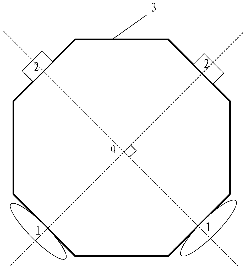
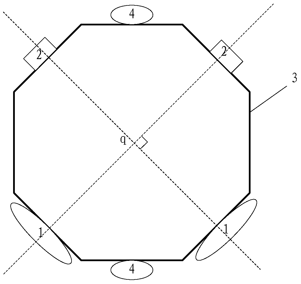
[0048] refer to figure 1 , is a structural schematic diagram of Embodiment 1 of a camera motor provided by the present invention, wherein the camera motor in this embodiment can be installed in devices with image acquisition functions such as mobile phones, pads, and SLR cameras.

[0049] In this embodiment, the camera motor may include the following structures:

[0050] At least two optical image stabilizer coils 1 and at least two metal parts 2 .

[0051] ...


PUM


Abstract

The invention discloses a camera motor and electronic equipment. The camera motor comprises at least two optical image stabilizer coils and at least two metal parts, wherein the optical image stabilizer coils and the metal parts are distributed in the form of a ring-shaped structure; each optical image stabilizer coil and one metal part are oppositely arranged; a connecting line between each optical image stabilizer coil and the opposite metal part is mutually perpendicular and crossed on the center point of the ring-shaped structure; after being electrified, each optical image stabilizer coil can generate acting force with the corresponding metal part.

Description

technical field [0001] The invention relates to the technical field of mechanical design, in particular to a camera motor and electronic equipment. Background technique [0002] At present, in camera motors of mobile devices such as mobile phones, magnetic coils are usually used to provide anti-shake power. In the ring frame of the camera motor, there are four symmetrically distributed anti-shake magnetic coils. The two anti-shake magnetic coils opposite to each other will generate electromagnetic waves in the x-direction and y-direction after being energized to generate force to push the lens connected to the frame to move in the x-direction and y-direction to stabilize the lens. [0003] Therefore, in the camera motor, the electromagnetic wave in the x-direction crosses the electromagnetic wave in the y-direction, and the crossing of electromagnetic waves will cause instability of the motor and lens shake to a certain extent. Contents of the invention [0004] The objec...

Claims


Application Information

Patent Timeline
Patent Type & Authority Patents(China)
IPC IPC(8): G02B7/09G03B13/36G03B5/00
CPCG02B7/09G03B5/00G03B13/36
Inventor 陈杰峰
Owner LENOVO (BEIJING) LTD
Learn More