Mixing equipment for PVC pipe production
A technology of mixing equipment and PVC pipes, which is applied in the field of mixing equipment for PVC pipe production, can solve the problems of semi-fluid internal agglomeration, difficult liquid capture and dispersion, uneven mixing, etc., and achieve the effect of increasing water pressure
- Summary
- Abstract
- Description
- Claims
- Application Information
AI Technical Summary
Problems solved by technology
Method used
Image
Examples
Embodiment 1
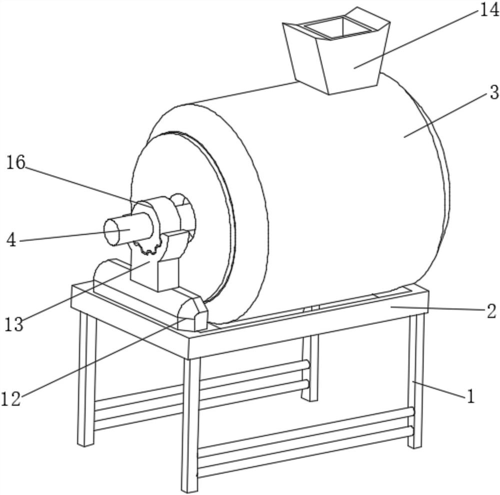
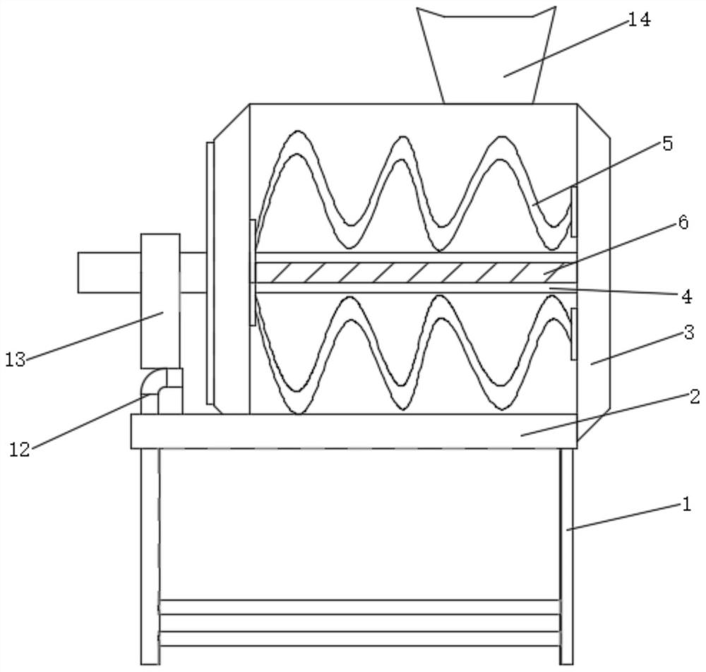
[0028] see Figure 1-3 , the present invention provides a technical solution: a mixing equipment for PVC pipe production, including a fixed frame 1, the top of the fixed frame 1 is fixedly connected with the fixed frame 2, the top of the fixed frame 2 is fixedly connected with a mixing box 3, the mixing box The inner surface of the body 3 is rotatably connected with the drive shaft 4, the upper and lower sides of the outer surface of the drive shaft 4 are fixedly connected with the stirring shaft 5, the right end of the stirring shaft 5 is rotatably connected with the inner surface of the mixing box 3, and the outer surface of the drive shaft 4 Both the left and right sides of the partition are fixedly connected with partitions 6, the outer surface of the partition 6 is uniformly provided with a circular groove 7, the inner surface of the circular groove 7 is fixedly connected with a mixing mechanism 8, and the outer surfaces of the two partitions 6 are located close to the mix...
Embodiment 2
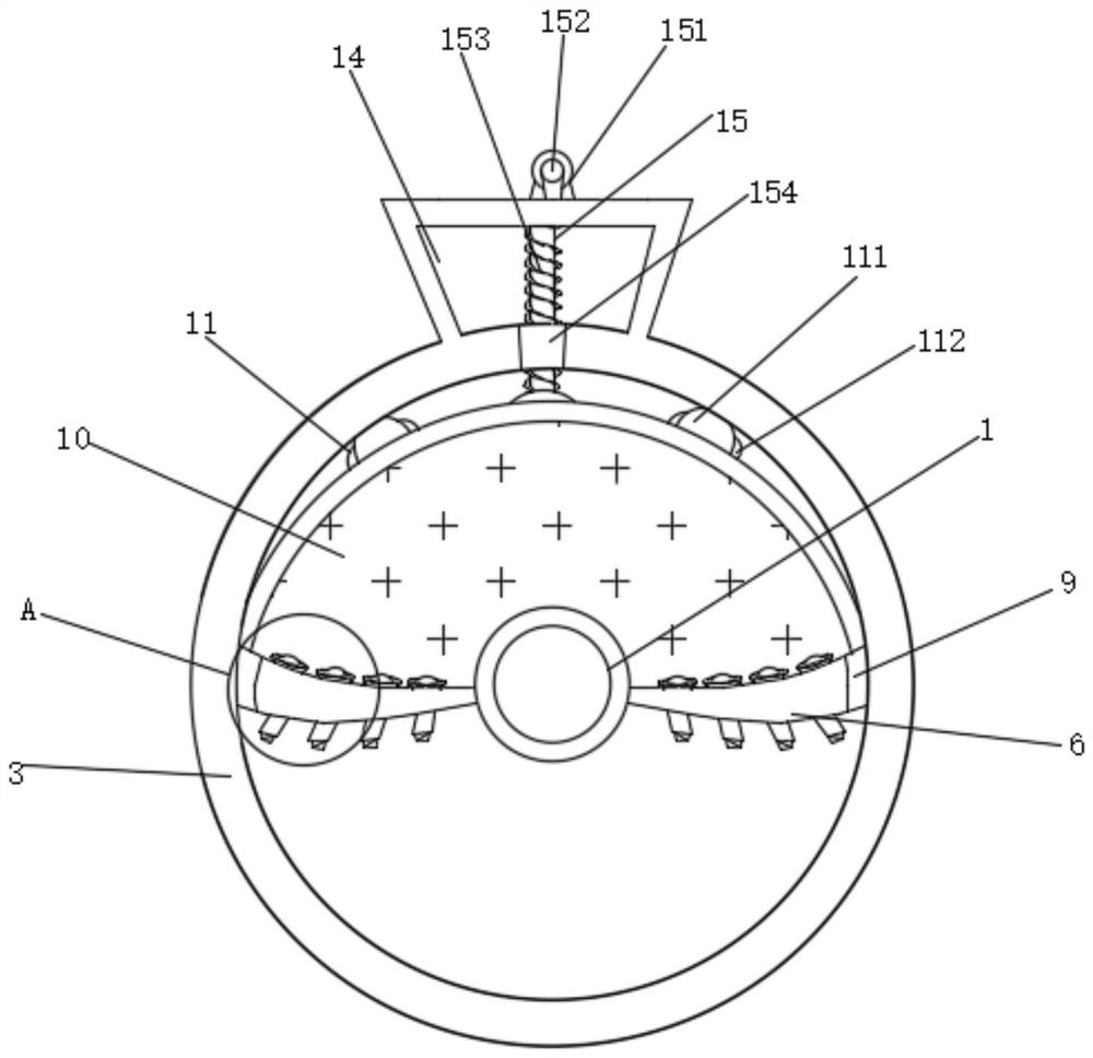
[0030] see Figure 3-6, the present invention provides a technical solution: the mixing mechanism 8 includes a cylindrical casing 81, the outer surface of the cylindrical casing 81 is fixedly connected with the inner surface of the circular groove 7, and the top of the cylindrical casing 81 is slidably connected with a sliding ball 82 , the left and right sides of the outer surface of the sliding ball 82 are fixedly connected with upper springs 83, and the outer surfaces of the two upper springs 83 are fixedly connected with the left and right sides of the inner surface of the cylindrical casing 81 respectively. The liquid above is mixed with the opening of the Y-shaped groove 86, and the left and right sides of the upper spring 83 can keep the sliding ball 82 to maintain the state that the Y-shaped groove 86 is opened.
[0031] An extruding mechanism 84 is slidably connected to the bottom of the inner surface of the cylindrical casing 81, and a lower spring 85 is fixedly conn...
Embodiment 3
[0035] see image 3 The present invention provides a technical solution: the stabilizing mechanism 11 includes a fixed airbag 111, the left and right sides of the fixed airbag 111 are provided with suction ports 112, and the outer surface of the fixed airbag 111 is fixedly connected with the outer surface of the arc casing 10. The suction port 112 is opened to inhale outside air, so that the fixed airbag 111 is stretched, and the two sides play a role in preventing shaking between the arc-shaped casing 10 and the mixing box 3, and the arc-shaped casing 10 will not rebound immediately. The safety performance of the equipment is improved.
[0036] The driving mechanism 15 includes a base 151, the bottom of the base 151 is fixedly connected to the top of the tapered casing 14, the inner surface of the base 151 is rotatably connected to a threaded cross bar 152, and the outer surface of the threaded cross bar 152 is rotatably connected to a threaded vertical rod 153, mixing The t...
PUM
 Abstract
Description
Claims
Application Information
 - R&D
- Intellectual Property
- Life Sciences
- Materials
- Tech Scout
- Unparalleled Data Quality
- Higher Quality Content
- 60% Fewer Hallucinations
Browse by: Latest US Patents, China's latest patents, Technical Efficacy Thesaurus, Application Domain, Technology Topic, Popular Technical Reports.
© 2025 PatSnap. All rights reserved.Legal|Privacy policy|Modern Slavery Act Transparency Statement|Sitemap|About US| Contact US: help@patsnap.com


