
Heat pump air conditioning system and control logic

A heat pump air conditioner and control logic technology, applied in the field of heat pump air conditioners, can solve problems such as difficult to ensure indoor environment comfort, increase system difficulty and cost, reduce equipment heating capacity, etc., to ensure heating effect, improve cooling effect, improve The effect of the heating effect

Inactive Publication Date: 2021-06-18
GUANDONG GIWEE TECH CO LTD
View PDF7 Cites 0 Cited by
  • Summary
  • Abstract
  • Description
  • Claims
  • Application Information

AI Technical Summary

Problems solved by technology

[0002] At present, there is basically no heating equipment in the southern part of my country, so the use of heat pump heating has become the first choice for high efficiency and energy saving. In winter rainy weather, the indoor environment needs heating supply. At this time, the outdoor unit is very prone to frost, which greatly reduces the heating capacity of the equipment and easily causes dissatisfaction and complaints from users. Therefore, how to maintain the existing equipment without increasing the complexity? Under the premise of any production cost, improving the heating capacity of low-temperature working conditions has become the research focus of various manufacturers. The existing solutions are mainly: one is to use two-stage compression; the other is frequent defrosting, in which two-stage compression It will greatly increase the difficulty and cost of the column system, and frequent defrosting is difficult to ensure the comfort of the indoor environment, which reduces the user experience. Therefore, it is necessary to adopt new technical means to efficiently defrost the low-temperature winter rainy weather

Method used


Image

  • Heat pump air conditioning system and control logic
  • Heat pump air conditioning system and control logic
  • Heat pump air conditioning system and control logic

Examples


Embodiment Construction

[0020] Preferred embodiments of the present invention are described below with reference to the accompanying drawings. Those skilled in the art should understand that these embodiments are only used to explain the technical principles of the present invention, and are not intended to limit the protection scope of the present invention.

[0021] It should be noted that in the description of the present invention, the term "inside" and other terms indicating the direction or positional relationship are based on the direction or positional relationship shown in the drawings, which is only for the convenience of description, rather than indicating or implying the The described devices or elements must have a specific orientation, be constructed and operate in a specific orientation and therefore should not be construed as limiting the invention. In addition, the terms "first", "second", "third", and "fourth" are used for descriptive purposes only, and should not be construed as in...


PUM


Abstract

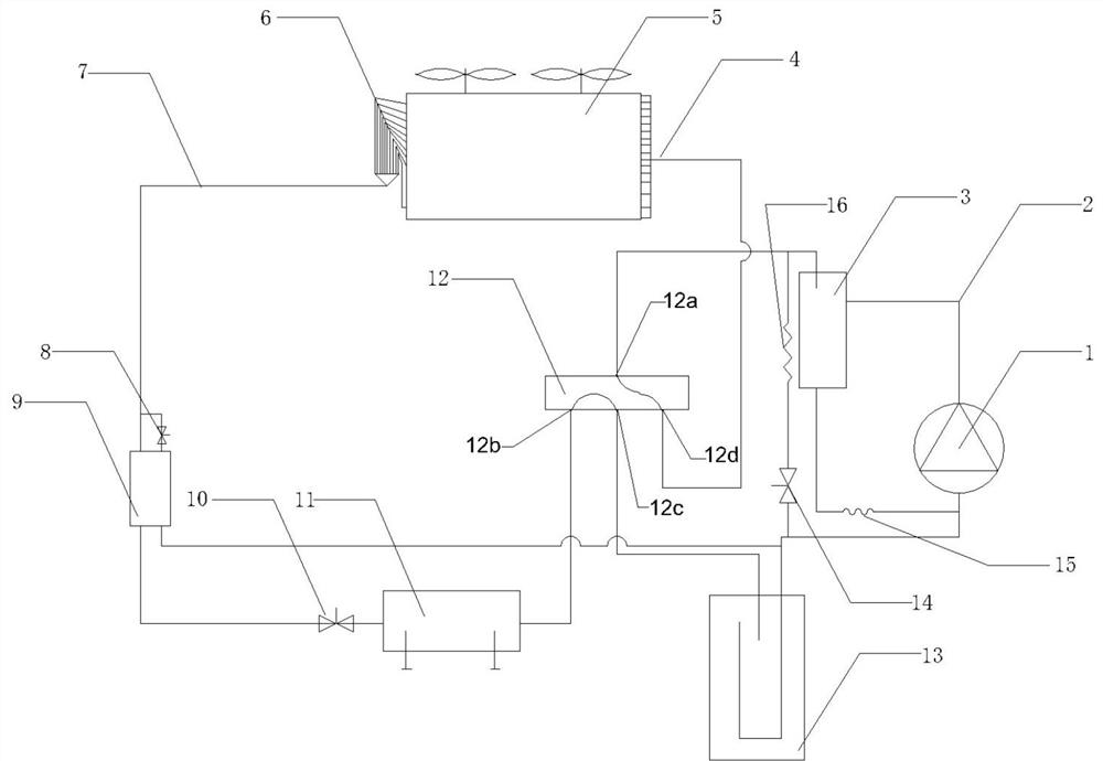
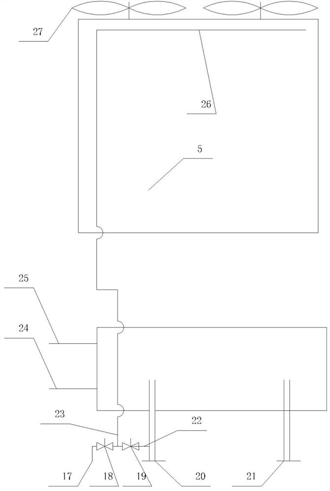
The invention provides a heat pump air conditioning system which can stably and efficiently operate under any working condition. When the environmental temperature is low, small part of hot water prepared by the system is sprayed to the surface of an air-cooled heat exchanger, a frost layer on the surface of the heat exchanger is dissolved and removed, and the heating capacity of the system is improved. When the environmental temperature is quite high, small part of cold water prepared by the system is utilized to conduct auxiliary cooling on the air-cooled heat exchanger, the condensing temperature of the system is reduced, then the operation reliability and the operation efficiency of the system are improved, and the defrosting effect and the heating effect of the air-cooled heat exchanger under various low-temperature working conditions are fully guaranteed. Meanwhile, the cooling effect under the high-temperature working condition can be improved, the annual operation efficiency of the system can be comprehensively improved, and the multiple purposes of improving the heating effect, the operation comfort and other performance of a cold system can be achieved.

Description

technical field [0001] The invention relates to the technical field of heat pump air conditioners, and specifically provides a heat pump air conditioner system and control logic. Background technique [0002] At present, there is basically no heating equipment in the southern part of my country, so the use of heat pump heating has become the first choice for high efficiency and energy saving. In winter rainy weather, the indoor environment needs heating supply. At this time, the outdoor unit is very prone to frost, which greatly reduces the heating capacity of the equipment and easily causes dissatisfaction and complaints from users. Therefore, how to maintain the existing equipment without increasing the complexity? Under the premise of any production cost, improving the heating capacity of low-temperature working conditions has become the research focus of various manufacturers. The existing solutions are mainly: one is to use two-stage compression; the other is frequent def...

Claims


Application Information

Patent Timeline
Patent Type & Authority Applications(China)
IPC IPC(8): F25B13/00F25B41/20F25B49/02F25D21/10
CPCF25B13/00F25B49/02F25D21/10
Inventor 方挺杨焕弟漆石球刘益才
Owner GUANDONG GIWEE TECH CO LTD
Learn More