Pipeline air tightness detection device and method

A detection device, pipeline gas technology, applied in the direction of measurement device, fluid tightness test, pipeline system, etc., can solve problems such as ineffectiveness

Pending Publication Date: 2021-06-18
STATE GRID CORP OF CHINA +1
View PDF0 Cites 1 Cited by
  • Summary
  • Abstract
  • Description
  • Claims
  • Application Information

AI Technical Summary

Problems solved by technology

There is also an acoustic wave detection method in the prior art. The principle is to use the listening rod to obtain the sound of water leakage in the pipeline to judge the leak point. If the pipeline is slightly leaky or the pipeline is pre-buried, this method cannot be effectively carried out.

Method used


Image

  • Pipeline air tightness detection device and method
  • Pipeline air tightness detection device and method
  • Pipeline air tightness detection device and method

Examples


Embodiment 1

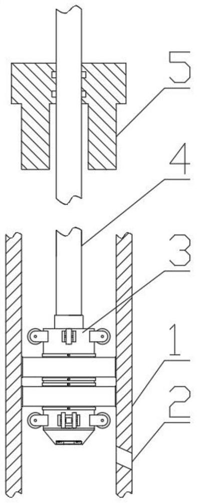
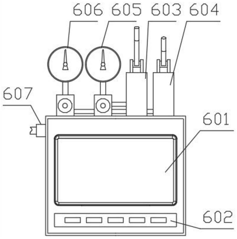
[0046] see Figure 1-Figure 17 , the embodiment of the present invention provides a pipeline airtightness detection device, including a detection head 3 that can extend into the pipeline 1 from the entrance of the pipeline 1 and block the pipeline 1, a hose 4 for supplying gas, and A detector 6 for detecting air pressure, the gas outlet of the detection head 3 located in the blocked pipeline 1 communicates with the gas outlet of the hose 4, and the air inlet of the hose 4 communicates with the detector 6 detection end docking. In this embodiment, the function of the detection head 3 is to find the location of the leakage point 2 in the pipeline 1, and the hose 4 has many functions, it can be used to provide gas, and can also be used as a passage for power lines and signal lines to pass through , can also play a role in cooperating with the movement of the detection head 3. These following embodiments will be described in detail. In this embodiment, one of its functions is to ...

specific Embodiment

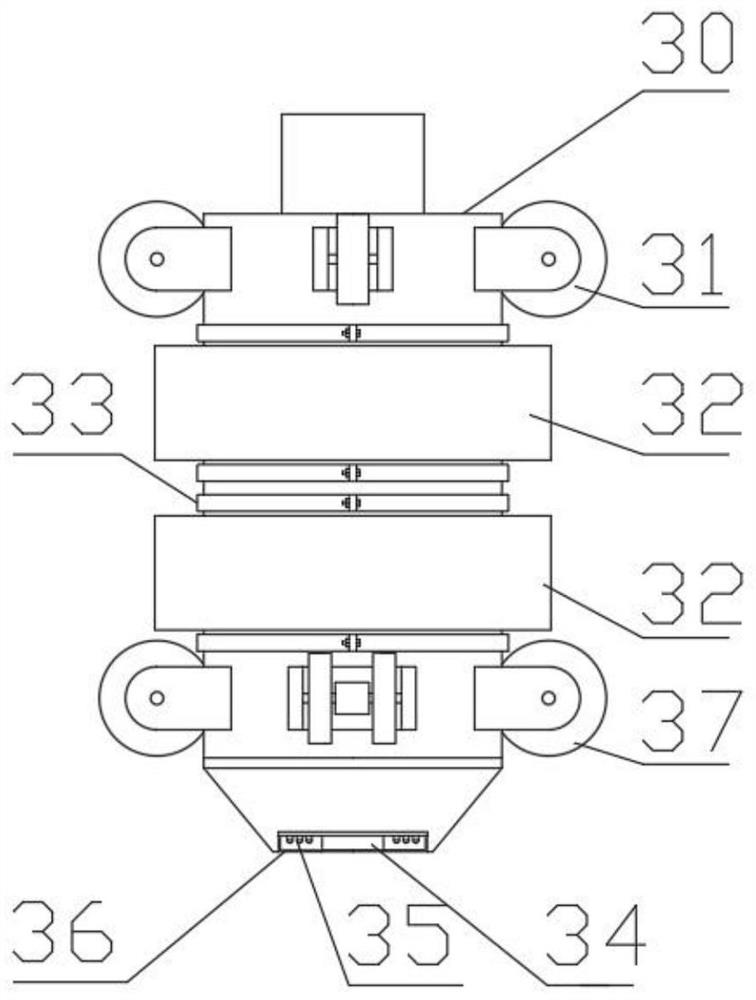
[0048] To refine the detection head 3 above, please refer to figure 1 , image 3 , Figure 4 and Figure 8 , the detection head 3 includes a main body 30 and an expansion ring 32 that can expand to block the pipeline 1 after inflating, the expansion ring 32 is sleeved on the main body 30, and the main body 30 has a first channel 304 and the third channel 306, the air inlets of the first channel 304 and the third channel 306 are connected with the air outlet of the hose 4, and the air outlet of the first channel 304 is located at the expansion On the circle 32, the gas outlet of the third channel 306 is the gas outlet located in the blocked pipeline 1 . In this embodiment, the hose 4 can not only fill the blocked pipeline 1 with gas, but also fill the expansion ring 32 with gas, and the expansion ring 32 will expand after being filled with gas, and its outer edge will become larger until it sticks to the wall. The inner wall of the pipeline 1 is connected to the inner wall ...

Embodiment 2

[0063] An embodiment of the present invention provides a pipeline airtightness detection method, comprising the following steps:

[0064] S1, extend the detection head 3 into the pipeline 1 from the entrance of the pipeline 1; S2, block the pipeline 1 to be detected in this section after the detection head 3 reaches the designated detection point; S3, block the section to the pipeline Fill the pipeline 1 with gas, and use the detector 6 to detect the air pressure change in the blocked pipeline 1; S4, observe the situation of the air pressure change reflected by the detector 6, if the section is blocked If the air pressure of the pipeline 1 continues to rise and does not fall back after rising, it is judged that the blocked pipeline 1 has no leak point 2, and then the blocked state is released, and the steps S2 and S3 are repeated; If the air pressure of pipeline 1 remains unchanged or rises slightly and then falls back, it can be judged that there is a leak point 2 in the bloc...


PUM


Abstract

The invention relates to the technical field of pipeline detection, and provides a pipeline airtightness detection device. The device comprises a detection head capable of extending into a pipeline from an inlet of the pipeline and plugging the pipeline, a hose for providing gas and a detector for detecting air pressure, and the detection head is positioned at an air outlet in the plugged pipeline and is communicated with an air outlet of the hose; and the air inlet of the hose is butted with the detection end of the detector. The invention also provides a pipeline air tightness detection method. The method comprises four steps of S1 to S4. According to the invention, the detection head extends into a to-be-detected pipeline and blocks the pipeline section, then the pipeline section is filled with gas through the hose, and then the pressure change of the pipeline section is directly detected through the detector, so that whether the pipeline section leaks or not can be quickly and accurately judged; and gas is provided for an expansion ring through the hose, and the expanded expansion ring can block the pipeline, so that the section, far away from the inlet of the pipeline, of the pipeline becomes a blocked section, and gas pressure detection is facilitated.

Description

technical field [0001] The invention relates to the technical field of pipeline detection, in particular to a pipeline airtightness detection device and method. Background technique [0002] A pipeline is a device used to transport gas, liquid or fluid with solid particles connected by pipes, pipe connectors and valves. Pipes are widely used in water supply, drainage, heat supply, gas supply, long-distance transportation of oil and natural gas, agricultural irrigation, hydraulic engineering and various industrial devices. During the use of the pipeline, due to natural reasons such as aging and corrosion, or artificial construction, the problem of damage cannot be avoided. After the pipeline is damaged, it is necessary to find the damaged point and locate the damaged location in time to make up for the loss of property and avoid potential safety hazards. [0003] However, the existing pipeline damage location methods mainly rely on manual inspections, public reports, regula...

Claims


Application Information

Patent Timeline
Patent Type & Authority Applications(China)
IPC IPC(8): G01M3/28F17D5/02
CPCF17D5/02G01M3/2815
Inventor 杨毅刘华宜王涛古小琴蔡静邵璐
Owner STATE GRID CORP OF CHINA
Why Eureka
Try Eureka