
Multi-hole sleeve labyrinth type regulating valve

A labyrinth, regulating valve technology, applied in the field of regulating valves, can solve the problem of not being able to adjust each valve

Active Publication Date: 2021-06-22
ZHEJIANG BETHEL TECH CO LTD
View PDF8 Cites 0 Cited by
  • Summary
  • Abstract
  • Description
  • Claims
  • Application Information

AI Technical Summary

Problems solved by technology

[0004] The object of the present invention is to provide a porous sleeve labyrinth regulating valve to solve the problem that the multi-regulating valves proposed in the above background technology are all of multi-hole sleeve design, but facing the design of the porous sleeve, the adjustment mechanism of many regulating valves However, the problem of not being able to adjust each valve well

Method used


Image

  • Multi-hole sleeve labyrinth type regulating valve
  • Multi-hole sleeve labyrinth type regulating valve
  • Multi-hole sleeve labyrinth type regulating valve

Examples


Embodiment Construction

[0028] The following will clearly and completely describe the technical solutions in the embodiments of the present invention with reference to the accompanying drawings in the embodiments of the present invention. Obviously, the described embodiments are only some, not all, embodiments of the present invention. Based on the embodiments of the present invention, all other embodiments obtained by persons of ordinary skill in the art without making creative efforts belong to the protection scope of the present invention.

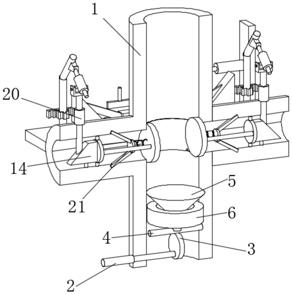
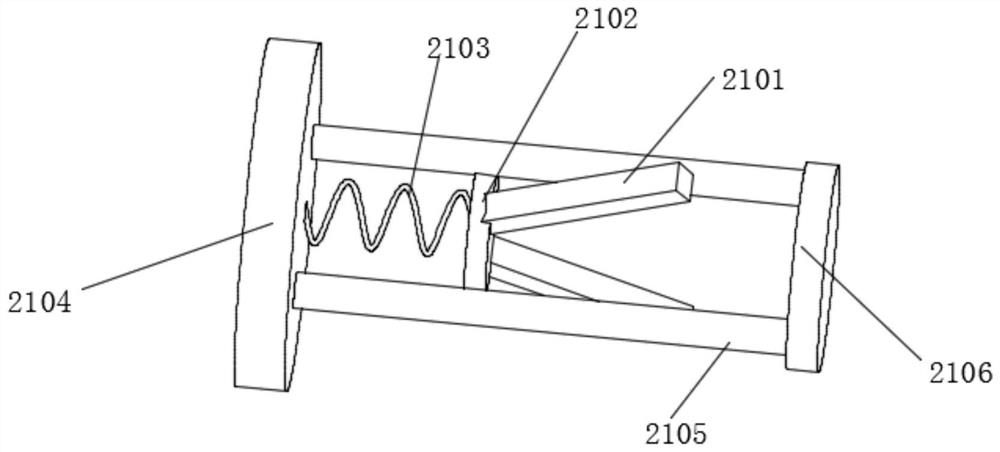
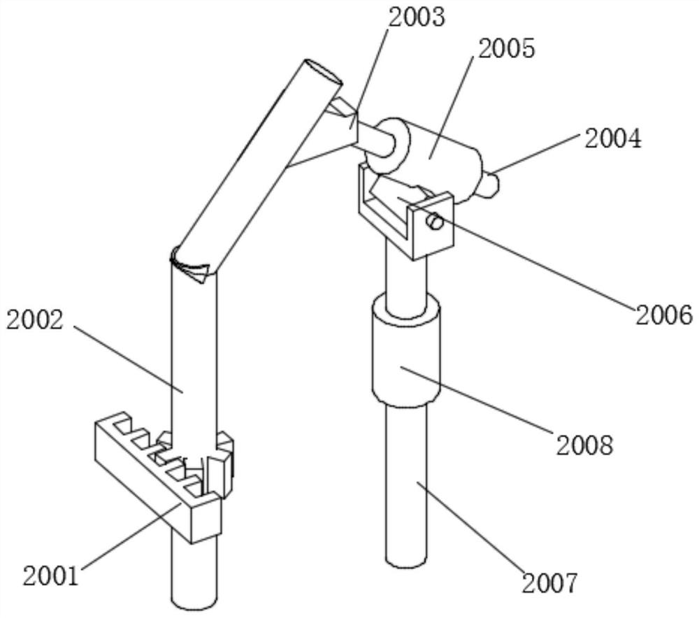
[0029] see Figure 1-8 , in an embodiment of the present invention, a labyrinth regulating valve with a porous sleeve includes a through pipe 1, a rotating rod 2 runs through the lower part of the through pipe 1, and a push plate 3 is fixedly connected to the side of the rotating rod 2, and the rotating rod 2 deviates from Based on the design of the center of the push plate 3, the limit rod 4 is slidingly connected to the inner wall of the through pipe 1, and ...


PUM


Abstract

The invention discloses a multi-hole sleeve labyrinth type regulating valve which comprises a through pipe. A rotating rod penetrates through the lower part of the through pipe, a push disc is fixedly connected to the side face of the rotating rod, a limiting rod is attached to the top of the push disc, a lifting column is fixedly connected to the top of the limiting rod, a connecting ring is fixedly connected to the position, located on the inner wall of the through pipe, of the lower part of the lifting column, a connecting plate is fixedly connected to one end of the through pipe, a hydraulic rod is installed at the top of the connecting plate, a push block is installed at the output end of the hydraulic rod, a transmission block is fixedly connected to one end of the push block, and a stress rod is attached to the side face of the transmission block. Through the arrangement of the lifting column, when the rotating rod is rotated, the rotating rod can drive the push disc to rotate; due to the eccentric design of the push disc, when the push disc rotates, the lifting column can be jacked up through the limiting rod; and due to the shape arrangement of the lifting column, when the distance between the lifting column and the connecting ring is larger, the flowing speed of liquid is larger, so that the purpose of adjusting the flowing speed is achieved.

Description

technical field [0001] The invention relates to the field of regulating valves, in particular to a labyrinth regulating valve with a porous sleeve. Background technique [0002] Control valve, also known as control valve, in the field of industrial automation process control, by receiving the control signal output by the adjustment control unit, with the help of power operation to change the final control element of process parameters such as medium flow, pressure, temperature, liquid level, etc., the control valve is suitable for In air, water, steam, various corrosive media, mud, oil and other media. [0003] Many of the current regulating valves are designed with multi-hole sleeves, but in the face of the design of porous sleeves, the adjustment mechanisms of many regulating valves cannot adjust each valve well. Therefore, we propose a multi-hole sleeve labyrinth regulator valve. Contents of the invention [0004] The purpose of the present invention is to provide a l...

Claims


Application Information

Patent Timeline
Patent Type & Authority Applications(China)
IPC IPC(8): F16K1/52F16K31/54F16K31/44F16K31/50
CPCF16K1/52F16K31/54F16K31/44F16K31/50
Inventor 尚玉来周广伶金瑞建林光办林超李平葛志克黄金柱周财慈
Owner ZHEJIANG BETHEL TECH CO LTD
Learn More