PT symmetric SS topology MC-WPT system and implementation method thereof
A MC-WPT and system implementation technology, applied in the direction of circuit devices, electrical components, etc., can solve problems such as loss, limited application fields, and lack of parameter design criteria, and achieve the effect of improving transmission distance
Active Publication Date: 2021-06-22
CHINA UNIV OF MINING & TECH
View PDF2 Cites 0 Cited by
- Summary
- Abstract
- Description
- Claims
- Application Information
AI Technical Summary
Problems solved by technology
[0005]1. There is no topology limitation in the existing PT symmetrical MC-WPT system based on the inverter mode, but it is necessary to control the frequency of the inverter and increase some Additional circuits, such as detection, control or regulation circuits, which will increase the complexity of the system and also bring additional losses
[0006]2. PT symmetrical system based on op amp mode Due to the existence of the virtual pole of the capacitor, the negative resistance constructed by using the op amp must be connected in parallel with the capacitor, otherwise the system cannot run stably
Therefore, the PT symmetrical MC-WPT based on the operational amplifie
Method used
View moreImage
Smart ImageViewing Examples
Examples
 PUM
 Abstract
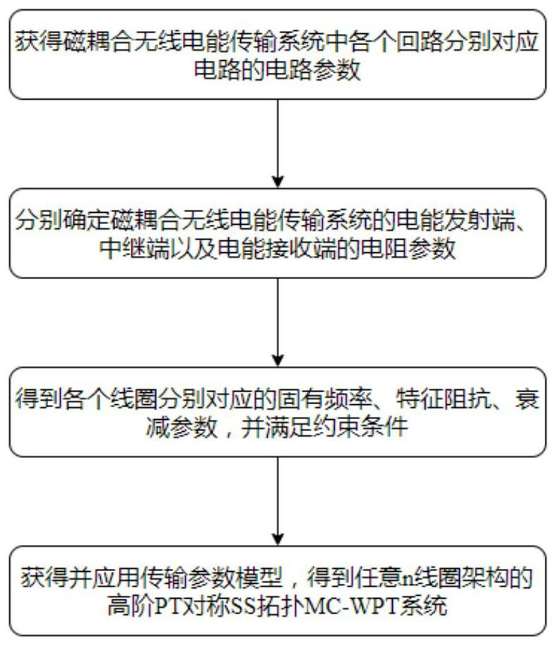
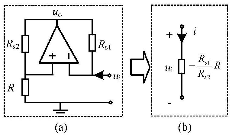
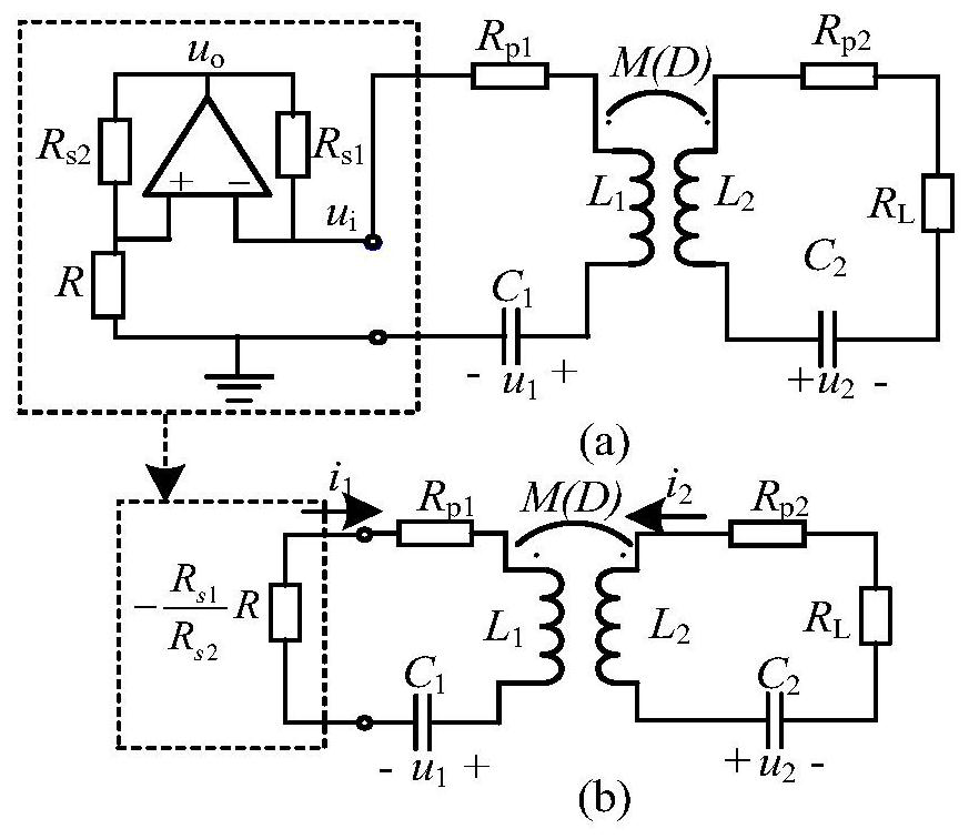
The invention discloses a PT symmetric SS topology MC-WPT system and an implementation method thereof. The PT symmetric characteristic is applied to a currently common two-coil SS topology magnetic coupling wireless power transmission system, and is further popularized to a high-order SS topology magnetic coupling wireless power transmission system of any n-coil architecture, wherein the PT symmetric SS topology MC-WPT system sometimes is a two-coil PT symmetric MC-WPT system, and sometimes is a high-order PT symmetric MC-WPT system with a relay coil. According to the technical scheme of the invention, the circuit structure of the negative resistor is changed, and the PT symmetry characteristic is applied to the most common SS topology magnetic coupling wireless power transmission system at present, so that the SS topology magnetic coupling wireless power transmission system can realize the high-efficiency energy transmission without any external setting, and a PT symmetry mechanism is further popularized to any multi-coil architecture wireless power transmission system, and accordingly a high-order SS topology magnetic coupling wireless power transmission system is obtained, and the transmission distance of the system can be effectively improved.
Description
technical field [0001] The invention relates to the field of wireless power transmission, in particular to a PT symmetrical SS topology MC-WPT system and an implementation method thereof. Background technique [0002] As we all know, the current commonly used MC-WPT systems usually can only achieve efficient energy transfer within a specific limited range. Once the transmission distance or azimuth deviates, the energy efficiency of the system will drop sharply, or even decrease as the transmission distance decreases. Limited by space transmission performance, such as transmission distance, offset, position robustness, etc., the industrialization process of MC-WPT technology is very slow. Effectively improving the space transmission performance of the system is the key to promoting the industrial application of MC-WPT technology . [0003] Regarding the improvement of the space energy transfer performance of the MC-WPT system, it is currently mainly focused on the system top...
Claims
Login to View More Application Information
Patent Timeline
 IPC IPC(8): H02J50/10H02J50/40H02J50/90H02J50/80
CPCH02J50/10H02J50/402H02J50/90H02J50/80
Inventor 廖志娟冯其凯姜陈慧吴凡马帅夏晨阳
Owner CHINA UNIV OF MINING & TECH
Features
- R&D
- Intellectual Property
- Life Sciences
- Materials
- Tech Scout
- Unparalleled Data Quality
- Higher Quality Content
- 60% Fewer Hallucinations
Learn More Browse by: Latest US Patents, China's latest patents, Technical Efficacy Thesaurus, Application Domain, Technology Topic, Popular Technical Reports.
© 2025 PatSnap. All rights reserved.Legal|Privacy policy|Modern Slavery Act Transparency Statement|Sitemap|About US| Contact US: help@patsnap.com


