Lightning rod fracture device with fracture protection

A lightning rod and sliding cavity technology, applied in the field of lightning rod breaking devices, can solve the problems of increased drop, lightning rod falling off, casualties, etc., and achieve the effect of preventing broken parts from falling, preventing device breaking, and reducing the magnitude of the force.

Inactive Publication Date: 2021-06-25
惠州市鑫泰电子贸易有限公司
View PDF0 Cites 0 Cited by
  • Summary
  • Abstract
  • Description
  • Claims
  • Application Information

AI Technical Summary

Problems solved by technology

[0002] When installing the lightning rod, it is necessary to install the lightning rod on the roof. Although this installation has a good lightning effect, it faces the risk that the lightning rod will fall off after a long period of wind and rain erosion, resulting in casualties and property losses. , and in typhoons and other windy climates, the probability of falling will also increase, especially in cities with high-rise buildings, and at this stage there is no device to prevent lightning rods from falling, only manual timing Inspections, dangerous and inefficient during inspections, cannot be conducted 24 / 7

Method used


Image

  • Lightning rod fracture device with fracture protection
  • Lightning rod fracture device with fracture protection
  • Lightning rod fracture device with fracture protection

Examples


Embodiment Construction

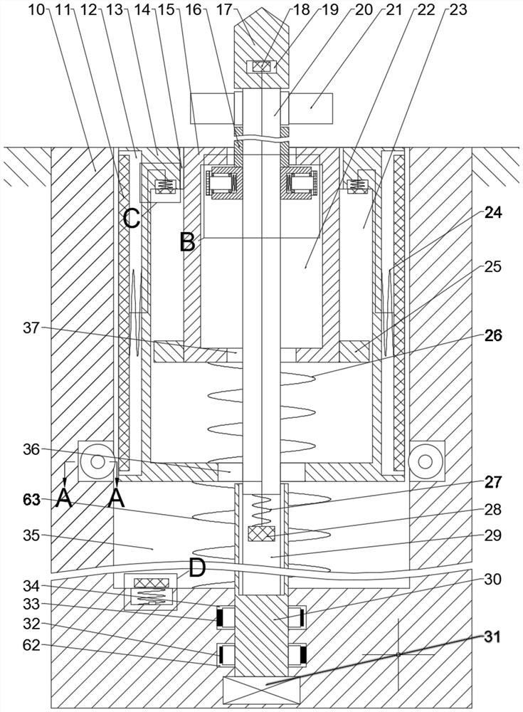
[0017] Combine below Figure 1-5 The present invention is described in detail, wherein, for the convenience of description, the orientations mentioned below are defined as follows: figure 1 The up, down, left, right, front and back directions of the projection relationship itself are the same.

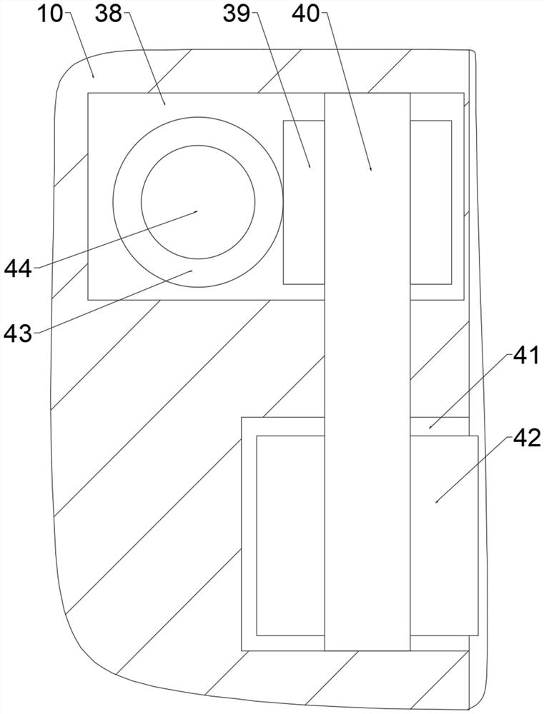
[0018] combined with Figure 1-5The lightning rod breakage device for breakage protection includes a main box body 10, a generator 31 is arranged inside the main box body 10, and a contraction main pulley cavity 62 is provided on the upper side of the generator 31, and the contraction The upper side of the primary pulley cavity 62 is provided with a contraction secondary pulley cavity 34, and the upper side of the contraction secondary pulley cavity 34 is provided with a contraction sliding cavity 35 with an opening upward and communicating with the outside world. Two shrinking spur gear chambers 41 are symmetrically arranged around the shrinking sliding chamber 35. The rear side of ...


PUM


Abstract

The invention relates to the related field of lightning arresters, and discloses a lightning rod fracture device with fracture protection. The device comprises a main box body, wherein a power generator is arranged in the main box body; a contraction main belt wheel cavity is arranged at the upper side of the power generator; a contraction auxiliary belt wheel cavity is arranged at the upper side of the contraction main belt wheel cavity; a contraction sliding cavity with an upward opening and communicated with the outside is arranged at the upper side of the contraction auxiliary belt wheel cavity; and the outer side of the contraction sliding cavity is communicated with two contraction spur gear cavities which are arranged in a bilateral symmetry mode with the contraction sliding cavity as the center. According to the device, the cavities are driven through internal threads to sense the magnitude of external wind power, the purpose of automatically judging whether the wind resistance strength of the part, exposed outside, of the lightning rod needs to be enhanced or not is achieved, then a centrifugal driving block drives a drive shaft and all parts in the drive shaft to move downwards, the stress of external parts is reduced, the purpose of preventing the device fracture under the condition that the function of the device is not affected is achieved, and finally the purpose of preventing the broken part from falling is achieved through the matching effect of a fracture check block, an anti-falling pull rope and an anti-falling check block.

Description

technical field [0001] The invention relates to the related field of lightning protection devices, in particular to a lightning rod breakage device for breakage protection. Background technique [0002] When installing the lightning rod, it is necessary to install the lightning rod on the roof. Although this installation has a good lightning effect, it faces the risk that the lightning rod will fall off after a long period of wind and rain erosion, resulting in casualties and property losses. , and in typhoons and other windy climates, the probability of falling will also increase, especially in cities with high-rise buildings, and at this stage there is no device to prevent lightning rods from falling, only manual timing Inspection, inspection is not only dangerous but also inefficient, and inspection cannot be carried out around the clock. Contents of the invention [0003] The object of the present invention is to provide a lightning rod breakage device for breakage pr...

Claims


Application Information

Patent Timeline
Patent Type & Authority Applications(China)
IPC IPC(8): F03D80/30F03D80/00F03D3/00F03D9/25F03D9/45
CPCF03D3/005F03D9/25F03D9/45F03D80/00F03D80/30Y02B10/30Y02E10/728Y02E10/74
Inventor 罗佳文
Owner 惠州市鑫泰电子贸易有限公司
Why Eureka
Try Eureka