High impedance state control circuit for RS-485 transceiver

A RS-485 and control circuit technology, applied to electrical components, transmission systems, etc., can solve the problems of limited use scenarios, and the difficulty of ESD voltage reaching 15,000 volts, and achieve the effect of increasing ESD voltage

Active Publication Date: 2021-06-25
苏州灵天微半导体科技有限公司
View PDF4 Cites 0 Cited by
  • Summary
  • Abstract
  • Description
  • Claims
  • Application Information

AI Technical Summary

Problems solved by technology

[0003] The RS-485 chip must be in a high-impedance state after the output drive is turned off. At this time, the voltage range it can withstand is stipulated in the protocol as -7v~12v. The existing RS-485 chip usually uses CMOS output, and the negative voltage will cause The parasitic diode of the NMOS tube is turned on and thus clamped, and a high voltage input greater than the power supply voltage will cause the parasitic diode between the drain and the N well to conduct
[0004] The current solution on the market is to connect a reverse diode to the output port to block the output port, form a connection with the parasitic diode, and block the voltage clamping; this method makes the ESD voltage of the two output ports of the bus A / B very low. It is difficult to reach 15,000 volts, which limits many usage scenarios

Method used


Image

  • High impedance state control circuit for RS-485 transceiver
  • High impedance state control circuit for RS-485 transceiver

Examples


Embodiment Construction

[0017] In order to make the purpose, technical solution and advantages of the present invention more clear, the present invention will be further described in detail below in conjunction with the accompanying drawings and embodiments. It should be understood that the specific embodiments described here are only used to explain the present invention, not to limit the present invention.

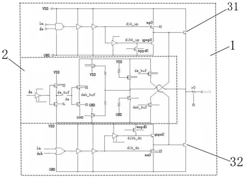
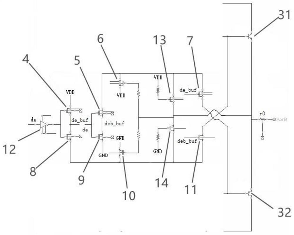
[0018] When this high-impedance state control circuit is implemented, based on the isolation process, it is necessary to connect the N wells of the PMOS devices such as the first PMOS transistor, the second PMOS transistor, the third PMOS transistor, the fourth PMOS transistor, and the fifth PMOS transistor to the first NMOS transistor. The P wells of NMOS such as the second NMOS transistor, the third NMOS transistor, the fourth NMOS transistor, and the fifth NMOS transistor are floating to block the clamping of the parasitic diode between the substrate and the well.

[0019] This example refer...


PUM


Abstract

The invention relates to a high-impedance state control circuit for an RS-485 transceiver. The high-impedance state control circuit comprises an RS-485 output driving module and a high-impedance state control module; a bus output stage of the RS-485 output driving module is electrically connected with an NPN triode and a PNP triode, and the high resistance state control module is used for enabling the NPN triode and the PNP triode to be cut off when the RS-485 output driving module is enabled to be closed. According to the high-resistance state control circuit for the RS-485 transceiver, the triode is adopted as a bus output stage and a high-resistance state control module, when the RS-485 transceiver is controlled to be in an enabling closing state within the A / B common-mode level range of -7v to 12v, the output of the RS-485 transceiver is in a high-resistance state, the ESD voltage of the A / B output port of the bus is greatly improved, and the application in most occasions is met.

Description

technical field [0001] The invention relates to an RS-485 transceiver, in particular to a high-impedance state control circuit for the RS-485 transceiver. Background technique [0002] RS-485 is a standard defining the electrical characteristics of drivers and receivers in a balanced digital multipoint system, defined by the Telecommunications Industry Association and the Electronic Industries Alliance. Digital communication networks using this standard can effectively transmit signals over long distances and in environments with high electronic noise; RS-485 makes it possible to connect local networks and configure multi-drop communication links. [0003] The RS-485 chip must be in a high-impedance state after the output drive is turned off. At this time, the voltage range it can withstand is stipulated in the protocol as -7v~12v. The existing RS-485 chip usually uses CMOS output, and the negative voltage will cause The parasitic diode of the NMOS transistor is turned on a...

Claims


Application Information

Patent Timeline
IPC IPC(8): H04B1/40H04B1/401
CPCH04B1/40H04B1/401
Inventor 顾永兴
Owner 苏州灵天微半导体科技有限公司
Why Eureka
Try Eureka