Transmission with monitoring function

A technology of transmission mechanism and function, which is applied in the field of transmission mechanism with monitoring function, can solve the problems of no active monitoring and warning functions, and achieve the effect of improving accuracy and preventing contamination problems

Active Publication Date: 2022-07-22
HIWIN TECH
View PDF6 Cites 0 Cited by
  • Summary
  • Abstract
  • Description
  • Claims
  • Application Information

AI Technical Summary

Problems solved by technology

However, this design can only absorb iron filings passively, without active monitoring and warning functions

Method used


Image

  • Transmission with monitoring function
  • Transmission with monitoring function
  • Transmission with monitoring function

Examples


Embodiment Construction

[0028] The foregoing and other technical contents, features and effects of the present invention will be clearly presented in the following detailed description of the preferred embodiments with reference to the drawings. The directional terms mentioned in the following embodiments, such as: up, down, left, right, front or rear, etc., are only for referring to the directions of the attached drawings. Accordingly, the directional terms used are intended to illustrate, but not to limit the invention. Furthermore, in the following embodiments, the same or similar elements will be given the same or similar reference numerals.

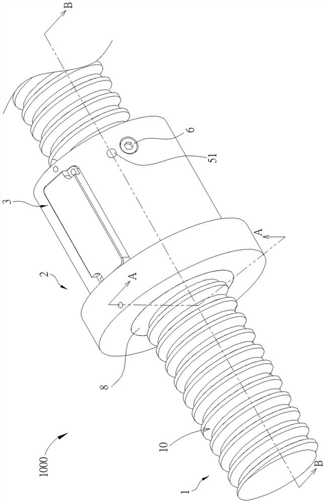
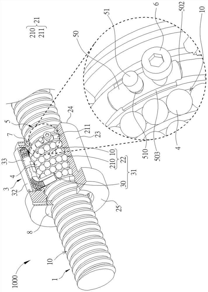
[0029] Please refer to Figure 1 to Figure 3 , figure 1 It is a schematic diagram of a transmission mechanism 1000 according to the first embodiment of the present invention, figure 2 It is an exploded schematic diagram of the transmission mechanism 1000 according to the first embodiment of the present invention, image 3 for figure 1 A partial cross-...


PUM


Abstract

The invention provides a transmission mechanism with monitoring function, comprising a long shaft, a moving part, a circulation device, a plurality of rolling bodies and a monitoring module. The long shaft has a rolling groove. The moving part is sleeved on the long shaft and has a rolling groove corresponding to the rolling groove, the rolling groove has an effective tooth segment and an ineffective tooth segment, and the effective tooth segment of the rolling groove and the rolling groove form a load path . The circulation device has a return passage, the return passage communicates with the load path and forms a circulation path with the load path, and the plurality of rolling bodies are arranged in the circulation path. The rolling groove and the rolling groove are covered with lubricating oil, and the monitoring module includes a liquid collecting body and a sensor, wherein the sensor is used for sensing the metal content in the lubricating oil flowing through the liquid collecting body.

Description

technical field [0001] The present invention relates to a transmission mechanism, in particular to a transmission mechanism with monitoring function. Background technique [0002] Generally, a linear actuator such as a ball screw is composed of a moving body such as a nut or nut, a long shaft member such as a screw, and a rolling member such as balls. Japanese Patent Laid-Open No. 5076887 discloses a ball screw in which lubricant is supplied from lubricant supply holes 20a, 20b by means of lubricant supply unit 23), and the lubricant discharged from lubricant discharge hole 21 is measured with an iron powder concentration meter 27 and a second iron powder concentration meter 32 is used to measure the iron powder concentration in the lubricant after passing through a filter device 29. When the difference between the iron powder concentration in the lubricant after passing through the filter device 29 and the iron powder concentration in the lubricant before passing through t...

Claims


Application Information

Patent Timeline
Patent Type & Authority Patents(China)
IPC IPC(8): F16H25/22F16H57/01F16H57/04
CPCF16H25/2214F16H57/01F16H57/0405F16H2057/012
Inventor 江宗宪郭名哲
Owner HIWIN TECH
Why Eureka
Try Eureka