Position calibration equipment for wafer box

A technology for calibrating equipment and film cassettes, which is applied in the direction of measuring devices, instruments, etc., can solve the problem that the position calibration equipment cannot be adjusted in real time, so as to prevent the failure of taking the film and ensure the effect of taking the film

Pending Publication Date: 2021-07-02
BEIJING NAURA MICROELECTRONICS EQUIP CO LTD
View PDF8 Cites 0 Cited by
  • Summary
  • Abstract
  • Description
  • Claims
  • Application Information

AI Technical Summary

Problems solved by technology

[0004] The invention discloses a position calibration device for a cassette to solve the problem that the current position calibration device cannot perform position adjustment in real time

Method used


Image

  • Position calibration equipment for wafer box
  • Position calibration equipment for wafer box
  • Position calibration equipment for wafer box

Examples


Embodiment Construction

[0034] In order to make the purpose, technical solution and advantages of the present invention clearer, the technical solution of the present invention will be clearly and completely described below in conjunction with specific embodiments of the present invention and corresponding drawings. Apparently, the described embodiments are only some of the embodiments of the present invention, but not all of them. Based on the embodiments of the present invention, all other embodiments obtained by persons of ordinary skill in the art without making creative efforts belong to the protection scope of the present invention.

[0035] The technical solutions disclosed by various embodiments of the present invention will be described in detail below in conjunction with the accompanying drawings.

[0036] Firstly, the calibration device used in the related art will be introduced.

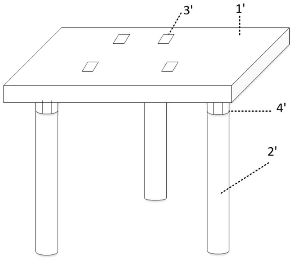
[0037] Such as figure 1 As shown, in the related art, the placement plate 1' is used to place the film box ...


PUM


Abstract

The invention discloses a position calibration device for a wafer box. The position calibration device comprises a supporting plate assembly, an adjusting mechanism and a detection mechanism; the supporting plate assembly is connected with the adjusting mechanism and is used for bearing the wafer box; the detection mechanism is used for detecting the actual position of the wafer box; and the adjusting mechanism is used for driving the wafer box to perform deflection motion and/or translational motion on the supporting plate assembly under the condition that the detection mechanism detects that the actual position is not at the preset position, so that the wafer box moves to the preset position from the actual position. Accurate positioning of the wafer box can be achieved, so that the accuracy of a wafer taking position is guaranteed, and wafer taking failure or wafer collision of a mechanical arm and other abnormalities are effectively prevented.

Description

technical field [0001] The invention relates to the technical field of semiconductors, in particular to a position calibration device for a chip box. Background technique [0002] Cassette position calibration equipment is widely used in the field of semiconductor technology. For example, when performing silicon sampling, it is necessary to place the cassette on the position calibration equipment to adjust the levelness, and then operate the manipulator to take out the silicon wafer from the cassette. [0003] However, in the current casket position calibration equipment, the calibration operation is performed before sampling. If the position of the cassette is deviated during the sampling process, it is necessary to manually pause and re-adjust, which will affect production efficiency. If the deviation is not detected If it is discovered in time, it may cause the failure of picking up the wafer or the collision of the manipulator, resulting in damage to the silicon wafer or...

Claims


Application Information

Patent Timeline
Patent Type & Authority Applications(China)
IPC IPC(8): G01B21/00G01B21/22
CPCG01B21/00G01B21/22
Inventor 尹子剑赵海洋
Owner BEIJING NAURA MICROELECTRONICS EQUIP CO LTD
Why Eureka
Try Eureka