Cassette Rotation Mechanism and Loading Chamber

A technology of rotating mechanism and loading chamber, which is applied in the direction of transportation and packaging, conveyor objects, electrical components, etc. It can solve the problems of unergonomic operation, different friction coefficients, and failure to return the film box, so as to improve the process The effect of making yield, reducing process cost, and improving chip yield

Active Publication Date: 2021-06-08
BEIJING NAURA MICROELECTRONICS EQUIP CO LTD
View PDF0 Cites 0 Cited by
  • Summary
  • Abstract
  • Description
  • Claims
  • Application Information

AI Technical Summary

Problems solved by technology

[0009] But in the chip box rotating mechanism of above-mentioned structure, at first, because the kind of wafer is different, coefficient of friction is different, under the situation that inclination angle is not enough when tilting, wafer may not be able to slide to the notch of chip box rear portion, and tilts The angle is limited by the center of gravity of the mechanism and cannot exceed the center of rotation, otherwise the film cassette cannot be returned when it is poured out
Secondly, the entire loading action requires the operator to put the cassette into the chamber, which requires a wide opening of the chamber, and the operation action is not ergonomic, which may easily cause mistakes and cause the wafer to slip out

Method used


Image

  • Cassette Rotation Mechanism and Loading Chamber
  • Cassette Rotation Mechanism and Loading Chamber
  • Cassette Rotation Mechanism and Loading Chamber

Examples


Embodiment Construction

[0074] Specific embodiments of the present invention will be described in detail below in conjunction with the accompanying drawings. It should be understood that the specific embodiments described here are only used to illustrate and explain the present invention, and are not intended to limit the present invention.

[0075] Such as Figure 6 to Figure 11 As shown, the first aspect of the present invention relates to a cassette rotating mechanism 100 . Wherein, the cassette rotating mechanism 100 includes a supporting base 110 , a rotating supporting base 120 and a moving assembly 130 .

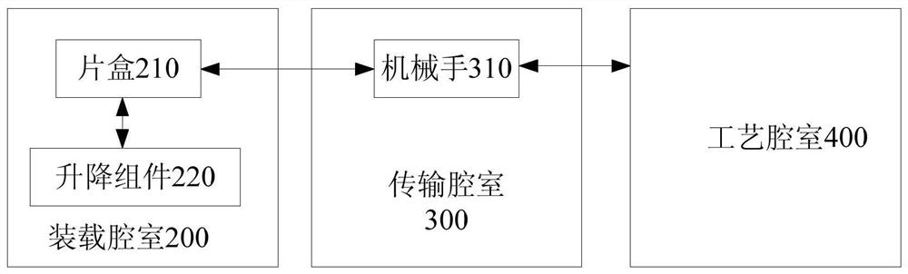
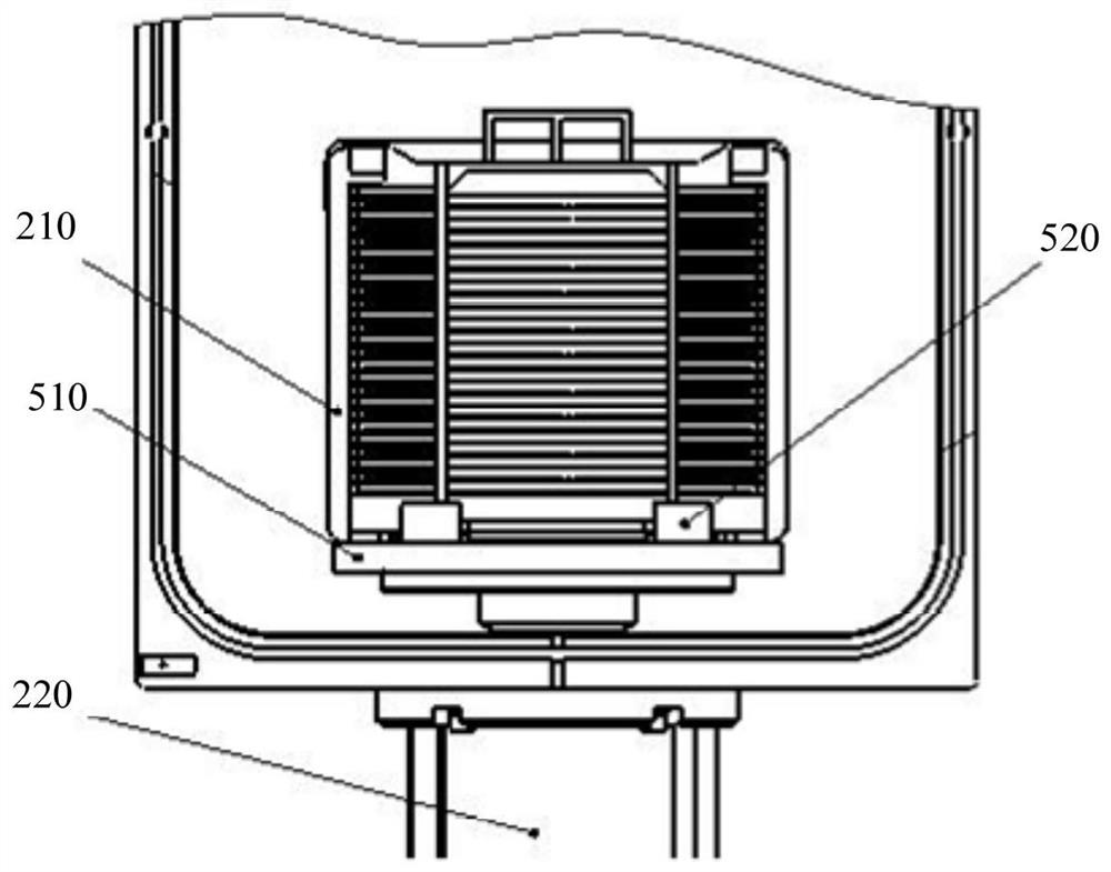
[0076] The support base 110 mentioned above can move linearly in the vertical direction under the action of the driving force. For example, the support base 110 can be connected with the lifting assembly 220 described below, which provides the driving force for the support base 110 . That is to say, driven by the lifting assembly 220 , the support base 110 can move linearly in the vertical...


PUM


Abstract

The invention discloses a film box rotating mechanism and a loading chamber. The film cassette rotating mechanism includes a supporting base, a rotating supporting base and a moving assembly; the supporting base can move linearly in the vertical direction under the action of the driving force, the rotating supporting base is located on the supporting base, and one end of the rotating supporting base is connected with the supporting base. One end is rotatably connected, and the rotating support base is used to load the film cassette; the moving assembly includes a guide rail, a moving part and an elastic part, the moving part is connected to the side of the rotating supporting base, and the guide rail is used to be fixedly arranged on the side wall of the loading chamber; During the downward movement of the support base, the guide rail can contact the moving part to prevent the moving part from moving downward, so that the rotating support base can be rotated from the vertical position to the flat position; Restoration force for swiveling from the flat position to the upright position. It can make the wafer have an accurate pick-up position in the cassette, improve the pick-up yield rate, and save the pick-up time.

Description

technical field [0001] The invention relates to the technical field of semiconductor equipment, in particular to a chip box rotating mechanism and a loading chamber comprising the chip box rotating mechanism. Background technique [0002] In the traditional semiconductor equipment transmission system, such as figure 1 As shown, the transmission system includes a loading chamber 200 , a transmission chamber 300 and a process chamber 400 , wherein a cassette 210 and a lifting assembly 220 are disposed in the loading chamber 200 , and a manipulator 310 is disposed in the transmission chamber 300 . Specifically, the lifting assembly 220 drives the cassette 210 to move linearly along the vertical direction, so as to facilitate the manipulator 310 in the transfer chamber 300 to take out wafers from the cassette 210 . Among them, taking out wafers from the cassette 210 is the first step in the automatic transfer process of many semiconductor devices, so the efficiency and reliabil...

Claims


Application Information

Patent Timeline
Patent Type & Authority Patents(China)
IPC IPC(8): H01L21/677
CPCH01L21/67775H01L21/67778
Inventor 李冬冬赵梦欣赵磊李萌
Owner BEIJING NAURA MICROELECTRONICS EQUIP CO LTD
Why Eureka
Try Eureka