Dual-purpose operating table of gynaecology and obstetrics
An operating table, obstetrics and gynecology technology, applied in the direction of operating table, surgery, medical science, etc.
- Summary
- Abstract
- Description
- Claims
- Application Information
AI Technical Summary
Problems solved by technology
Method used
Image
Examples
Embodiment 1
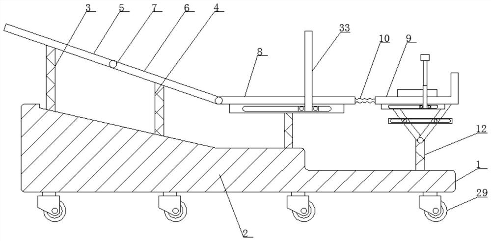
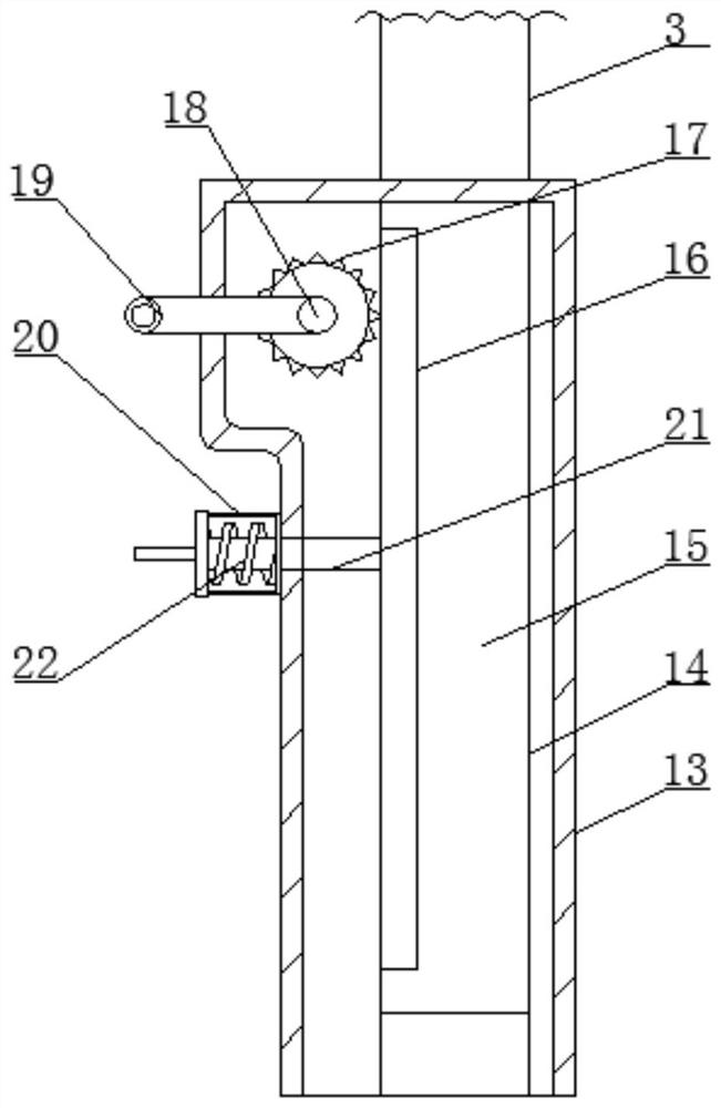
[0035] Such as Figure 1-7 As shown, the dual-purpose operating table for obstetrics and gynecology according to the embodiment of the present invention includes a bed frame 1 and a horizontal plate 2 located on one side of the bed frame 1, and the top of the bed frame 1 is provided with a symmetrically arranged column-3 And column two 4, the top of described column one 3 is provided with the backboard one 5 that is provided with inclination, the top of described column two 4 is provided with backboard two 6, and one side of described backboard two 6 is provided with described backboard two 6 The connecting shaft 7 connected to the backboard one 5, the side of the backboard two 6 away from the backboard one 5 is provided with a horizontally arranged seat plate 8, and one side of the seat plate 8 is provided with a support plate 9, The support plate 9 is connected with the seat plate 8 through the connecting belt 10, the bottom end of the support plate 9 is provided with a supp...
Embodiment 2
[0040] Such as Figure 1-7 As shown, one side of the clamp rod 21 is provided with a chute matching the rack 16, and the handle 19 is covered with a matching anti-slip sleeve, and one side of the connecting column 28 Fastening bolts are all provided, and the bottom end of the support plate 9 is provided with a horizontally arranged base plate 34, and both sides of the base plate 34 are provided with slideways 35, and the slideways 35 are provided with matching Slide block 36, one side of described slide block 36 is all provided with L-shaped support 37, and the top of described L-shaped support 37 is provided with foot support 38, and described foot support 38 is connected with described L-shaped support 37 by fixing mechanism. connect. Through the cooperative design of the slideway 35 and the slide block 36, the foot support 38 can be adjusted in left and right positions.
Embodiment 3
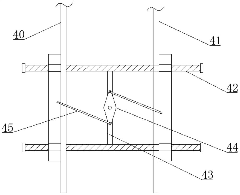
[0042] Such as Figure 1-7 As shown, the fixing mechanism includes a housing 39 positioned at the top of the L-shaped bracket 37, and the housing 39 is symmetrically provided with a vertical rod one 40 and a vertical rod two 41, the vertical rod one 40 and the top of the vertical rod 2 41 all extend to the outside of the housing 39 and are connected to the foot rest 38, and the housing 39 is symmetrically provided with the vertical rod 1 40 and the vertical rod 2 41 of the guide rod 42, the middle part between the two groups of guide rods 42 is provided with a connecting rod 43, one side of the connecting rod 43 is provided with a rotating piece 44, and both ends of one side of the rotating piece 44 are provided with The connecting rod 45 correspondingly connected with the vertical rod one 40 and the vertical rod two 41 respectively, the connecting rod 45 is connected with the connecting rod 43 through a connecting shaft, and one side of the connecting shaft extends to The ca...
PUM
 Abstract
Description
Claims
Application Information
 - R&D
- Intellectual Property
- Life Sciences
- Materials
- Tech Scout
- Unparalleled Data Quality
- Higher Quality Content
- 60% Fewer Hallucinations
Browse by: Latest US Patents, China's latest patents, Technical Efficacy Thesaurus, Application Domain, Technology Topic, Popular Technical Reports.
© 2025 PatSnap. All rights reserved.Legal|Privacy policy|Modern Slavery Act Transparency Statement|Sitemap|About US| Contact US: help@patsnap.com


