
Effective spraying device for wet tissue liquid during wet tissue production

A technology of spraying device and wet wipes, which is applied in the direction of processing textile material carriers, spraying/spraying textile materials, etc., which can solve the problems of troublesome and laborious manual unloading and the inability to fix the loading frame.

Active Publication Date: 2021-07-06
唐山安生纸制品制造有限公司
View PDF6 Cites 0 Cited by
  • Summary
  • Abstract
  • Description
  • Claims
  • Application Information

AI Technical Summary

Problems solved by technology

[0005] In order to overcome the shortcomings in the prior art that the loading frame cannot be fixed, the nozzle is fixed to wet the wet wipes, the liquid outlet pipe hangs down too much and touches the wet wipes, and manual feeding is troublesome and laborious. The technical problem of the present invention is to provide a Automatically wet wipes, automatically clamp and fix the loading frame, can spray wet wipes back and forth, tighten the liquid outlet pipe, and assist in the production of wet wipes for unloading. Effective spraying device for wet wipes

Method used


Image

  • Effective spraying device for wet tissue liquid during wet tissue production
  • Effective spraying device for wet tissue liquid during wet tissue production
  • Effective spraying device for wet tissue liquid during wet tissue production

Examples


Embodiment 1

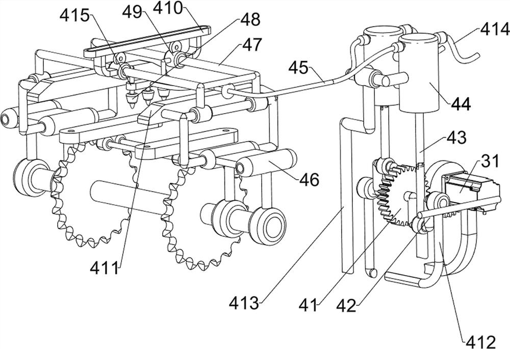
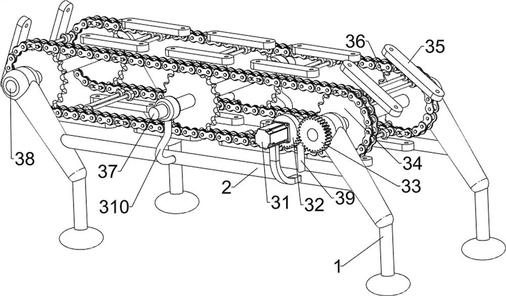
[0030]An effective spraying device for wet wipe liquid during wet wipe production, such as figure 1 , figure 2 and image 3 As shown, it includes a support foot 1, a crossbeam 2, a transmission mechanism 3 and a spray mechanism 4. The support feet 1 are symmetrically arranged on the front and rear sides of the ground, and the middle part of the support feet 1 on the front and rear sides is connected with a crossbeam 2. A transmission mechanism 3 is provided between the upper part of the support foot 1 and the crossbeam 2 , and a spray mechanism 4 is provided between the right part of the front crossbeam 2 and the transmission mechanism 3 .

[0031] The transmission mechanism 3 includes a motor 31, a half gear 32, a first gear 33, a chain sprocket assembly 34, a placement block 35, a connecting shaft 36, a fixed shaft 37, a rotating shaft 38, a first support base 39 and a second support base 310, A motor 31 is installed on the right front side upper part of the front crossbe...

Embodiment 2

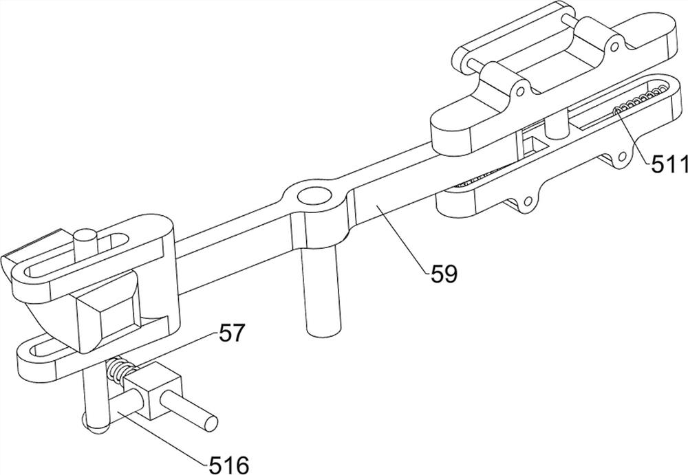
[0035] On the basis of Example 1, such as figure 1 , Figure 4 , Figure 5 , Figure 6 , Figure 7 and Figure 8 As shown, the clamping assembly 5 is also included, and the clamping assembly 5 includes a right-angle rod 51, a first spring 52, a connecting plate 53, a second wedge 54, a third wedge 55, a fourth wedge 56, a second wedge Spring 57, connection seat 58, swing bar 59, press seat 510, the third spring 511, wedge-shaped pressing block 512, the fourth spring 513, the third support frame 514, support rod 515 and slide bar 516, place block 35 left and right sides The right-angled rods 51 are all slidably connected, and the right-angled rods 51 cooperate with the first wedge-shaped block 411. The connecting plates 53 are connected between the insides of the right-angled rods 51, and there are first left-right symmetrical connections between the connecting plates 53 and the placement block 35. Spring 52, the first spring 52 is enclosed within on the right-angle bar 51...


PUM


Abstract

The invention relates to a spraying device, in particular to an effective spraying device for wet tissue liquid during wet tissue production. The technical problem of the invention is to provide the effective spraying device for the wet tissue liquid in the wet tissue production process, wherein wet tissues can be automatically wetted, a loading frame can be automatically clamped and fixed, the wet tissues can be sprayed back and forth, a liquid outlet pipe can be tensioned, and discharging can be assisted. The effective spraying device for wet tissue liquid during wet tissue production comprises supporting legs, wherein the supporting legs are symmetrically arranged on two sides of the ground; a crossbeam connected between the middle parts of the supporting legs on the two sides; a conveying mechanism arranged between the upper parts of the supporting legs and the cross beam; a spraying mechanism arranged between a first part of the crossbeam on one side and the conveying mechanism. The loading frame rotates anticlockwise to the rightmost side, slides to a rolling rod and then rolls to a discharging groove, so that the loading frame can be stably taken down, the auxiliary discharging effect is achieved, and the device is more convenient and easier to use.

Description

technical field [0001] The invention relates to a spraying device, in particular to an effective spraying device for wet wipes liquid during production of wet wipes. Background technique [0002] Under the high temperature in summer, people sweat a lot. In order to cool down and wipe sweat, the demand for wet wipes has increased significantly, and wet wipes are not easy to break and easy to wipe dirt, which is very popular among people. [0003] In the process of producing wet wipes, it is necessary to spray the wet wipes liquid on the wet wipes. The existing wet wipes liquid spraying technology is to start the motor to transmit the charging frame to the lower side of the nozzle, and the wet wipes liquid from the nozzle Spray onto the wet wipes, and then remove the loading frame and take out the wet wipes to collect. In this technology, the loading frame is placed on the conveying equipment first, and if it is not fixed, the wet wipes are prone to offset, which will affect t...

Claims


Application Information

Patent Timeline
IPC IPC(8): D06B1/02D06B23/04
CPCD06B1/02D06B23/04Y02P70/10
Inventor 黄小良
Owner 唐山安生纸制品制造有限公司
Learn More