Convenient-to-compact floor laying device for building decoration

A technology for architectural decoration and laying devices, which is applied in the direction of architecture and building construction, and can solve the problems of reduced laying speed and increased laying time interval

Inactive Publication Date: 2021-07-06
程诗栋
View PDF1 Cites 4 Cited by
  • Summary
  • Abstract
  • Description
  • Claims
  • Application Information

AI Technical Summary

Problems solved by technology

[0005] The purpose of the present invention is to solve the disadvantages existing in the prior art that the floor needs to be continuously placed by using an intermittent motion mechanism, so that

Method used


Image

  • Convenient-to-compact floor laying device for building decoration
  • Convenient-to-compact floor laying device for building decoration
  • Convenient-to-compact floor laying device for building decoration

Examples


Embodiment 1

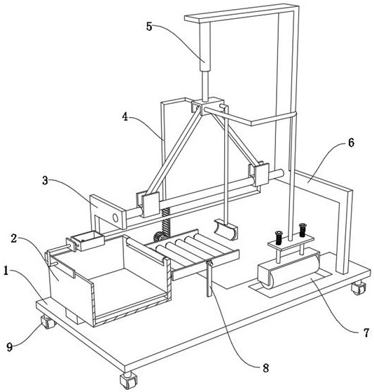
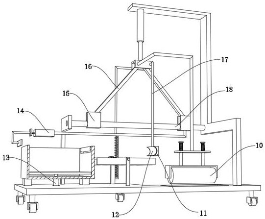
[0035] A floor laying device for architectural decoration that facilitates compaction, such as Figure 1-3As shown, it includes a moving seat 1, the outer wall of the top of the moving seat 1 is fixed with a mounting plate 3 and a mounting plate 2 6 by bolts, and the inner wall on one side of the mounting plate 3 and the inner wall on one side of the mounting plate 6 are fixed by bolts. The same sliding column 18, the outer wall of the sliding column 18 is slidably connected with two sliding seats 15, the inner wall of the top of the mounting plate 6 is fixed with a hydraulic cylinder 15 by bolts, and the output end of the hydraulic cylinder 15 is fixed by bolts There is a base 19, the inner wall of the base 19 is rotatably connected with two connecting rods 16, and the outer walls of the two connecting rods 16 are respectively rotatably connected to the inner walls of the two sliding seats 15, and the outer wall of the bottom of one of the sliding seats 15 is fixed by a bolt. ...

Embodiment 2

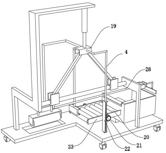
[0042] A floor laying device for architectural decoration that facilitates compaction, such as figure 1 , Figure 4 As shown, in order to compact the floor after laying; this embodiment makes the following supplements on the basis of embodiment 1: the outer wall of one side of the base 19 is fixed with a crimping frame 24 by bolts, and the top of the crimping frame 24 The outer wall is slidingly connected with two guide posts 27, the top inner wall of the guide post 27 and the bottom inner wall of the crimping frame 24 are clamped with the same spring 25, and the bottom outer walls of the two guide posts 27 are fixed with the same fixing frame 26 by bolts , the inner walls on both sides of the fixed frame 26 are rotatably connected with the same compacting roller 10; by being provided with a crimping frame 24, the compacting roller 10 can be crimped on the floor surface after laying when the base 19 is moved down. A spring 25 is provided to control the pressure of the compact...


PUM


Abstract

The invention discloses a convenient-to-compact floor laying device for building decoration, and relates to the technical field of floor laying devices. The floor laying speed is increased. The device specifically comprises a moving seat, a first mounting plate and a second mounting plate are fixed to the outer wall of the top of the moving seat through bolts, a same sliding column is fixed to the inner wall of one side of the first mounting plate and the inner wall of one side of the second mounting plate through bolts, two sliding seats are slidably connected to the outer wall of the circumference of the sliding column, a first hydraulic cylinder is fixed to the inner wall of the top of the second mounting plate through bolts, a base is fixed to the output end of the first hydraulic cylinder through bolts, two connecting rods are rotationally connected to the inner wall of the base, and the outer walls of the two connecting rods are rotationally connected to the inner walls of the two sliding seats correspondingly. The first hydraulic cylinder is arranged to drive the base to move downwards, so that the two sliding seats can slide back and forth along the circumferential outer wall of the sliding column under the adjusting action of the connecting rod.

Description

technical field [0001] The invention relates to the technical field of floor laying devices, in particular to a compact floor laying device for architectural decoration. Background technique [0002] After the building is built, not only the exterior wall of the building needs to be decorated, but also the interior of the building needs to be decorated. The indoor ground of some buildings needs to be laid with wooden floors. The current floor laying device needs to manually move the floor to the laying site , and then laying the floor, when the weight of the floor is heavy and the size is large, it will greatly increase the laying difficulty of the laying personnel, so it is necessary to design a floor laying device that can effectively reduce the labor intensity of the laying personnel. [0003] After searching, the Chinese patent application number is CN202020733521.9, which discloses a floor laying device for building decoration that is convenient for compaction, includin...

Claims


Application Information

Patent Timeline
IPC IPC(8): E04F21/22
CPCE04F21/22
Inventor 程诗栋
Owner 程诗栋
Why Eureka
Try Eureka