Eureka AIR delivers breakthrough ideas for toughest innovation challenges, trusted by R&D personnel around the world.

Foundation pit safety fence for bridge engineering construction site

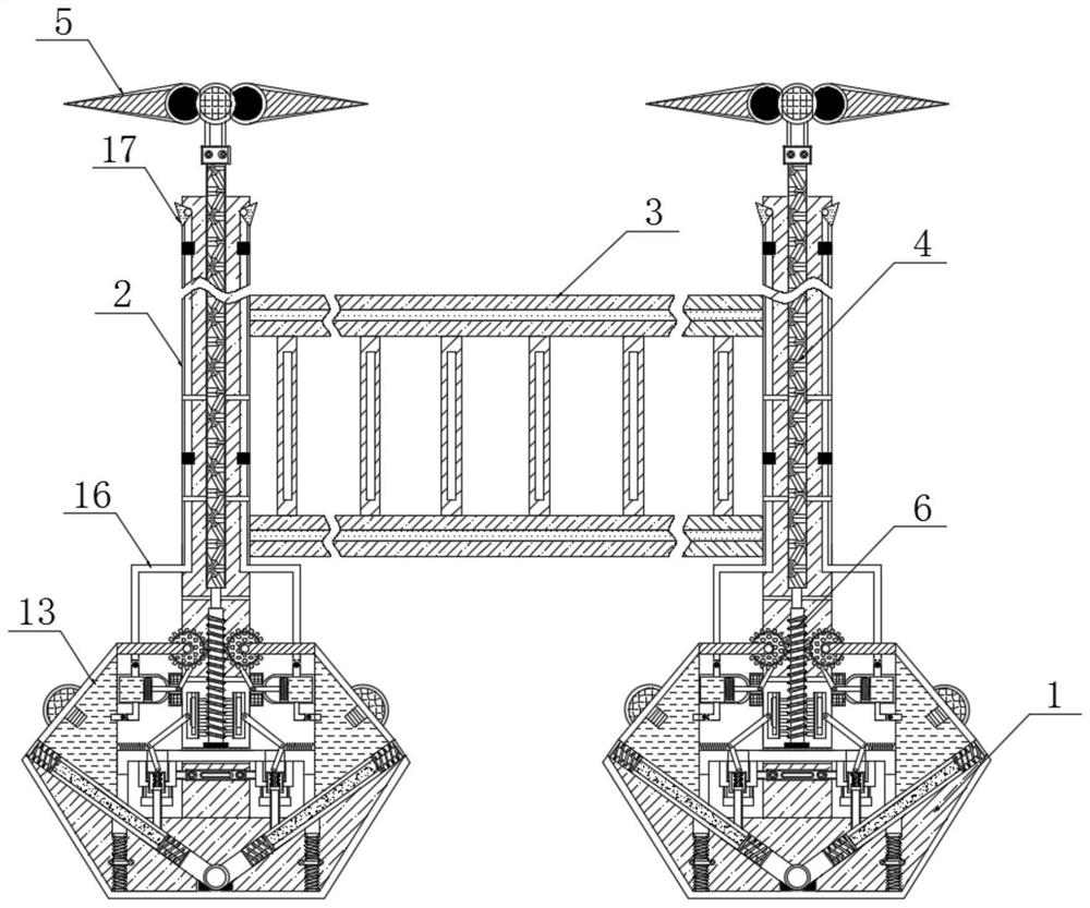
A technology for construction sites and bridge engineering, applied to fences, infrastructure engineering, and the use of liquid separation agents, etc., can solve problems affecting workers' health and construction progress, loose soil around foundation pits, and inability to settle dust

Inactive Publication Date: 2021-07-06
上海旌轩企业管理咨询中心
View PDF0 Cites 6 Cited by
  • Summary
  • Abstract
  • Description
  • Claims
  • Application Information

AI Technical Summary

Problems solved by technology

[0003] During the construction of the foundation pit, the site is relatively open, and there is no obstacle when the wind blows. Usually, the wind near the foundation pit is relatively strong, and the fence is easily toppled when it is blown by the wind, and the soil around the foundation pit is loose, so it is difficult to reinforce the fence. After the dust is raised, it floats in the air, and the dust floating in the air cannot be settled, which affects the health of workers and the progress of construction. Therefore, those skilled in the art provide a safety fence for foundation pits for bridge engineering construction sites to solve the problem. Problems raised in the background art above

Method used


Image

  • Foundation pit safety fence for bridge engineering construction site
  • Foundation pit safety fence for bridge engineering construction site
  • Foundation pit safety fence for bridge engineering construction site

Examples


Embodiment Construction

[0021] The following will clearly and completely describe the technical solutions in the embodiments of the present invention with reference to the accompanying drawings in the embodiments of the present invention. Obviously, the described embodiments are only some, not all, embodiments of the present invention. Based on the embodiments of the present invention, all other embodiments obtained by persons of ordinary skill in the art without making creative efforts belong to the protection scope of the present invention.

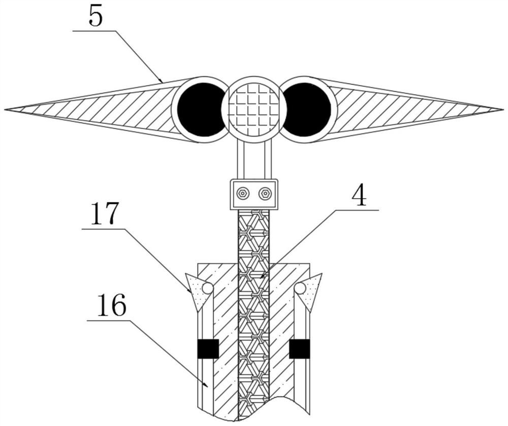
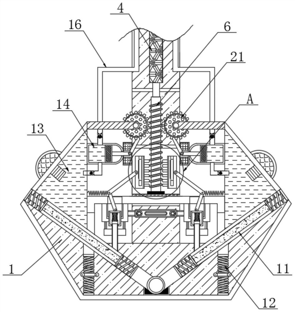
[0022] see Figure 1-6 , a foundation pit safety fence for a bridge engineering construction site, comprising a base 1, the inside of the base 1 is movably embedded with a fence rod 2, the outer surface of the fence rod 2 is movably connected with a fence frame 3, and the inside of the fence rod 2 is movably connected with Wind direction rod 4, the top of wind direction rod 4 is fixedly connected with wind direction wheel 5, the bottom end of wind direction ro...


PUM


Abstract

The invention relates to the technical field of foundation pit fences, in particular to a foundation pit safety fence for a bridge engineering construction site. A fence rod is movably embedded and connected in a base, a fence frame is movably connected to the outer surface of the fence rod, a wind direction rod is movably connected in the fence rod, and a wind direction wheel is fixedly connected to the top end of the wind direction rod. Threaded rods are fixedly connected to the bottom end of the wind direction rod and extends into the base, toothed plates are engaged to the two sides of the outer surface of the threaded rods, first connecting rods are movably connected to the outer surfaces of the toothed plates, second connecting rods are movably connected to the bottom ends of the first connecting rods, and pressing rods are movably connected to the bottom ends of the second connecting rods. Reinforcing plates are fixedly connected to the bottom ends of the pressing rods, the first connecting rods and the second connecting rods drive the pressing rods to downwards push the reinforcing plates to be attached to the ground, then the contact area between the base and the ground is increased, the effect of resisting wind blowing is achieved, and the fence is prevented from being blown down by strong wind.

Description

technical field [0001] The invention relates to the technical field of foundation pit fences, in particular to a foundation pit safety fence for a bridge engineering construction site. Background technique [0002] The foundation pit is an earth pit excavated at the foundation design position according to the base elevation and foundation plane size, while the bridge engineering foundation pit is mainly used for the construction of caps, abutments and expanded foundations. When workers work in the foundation pit, they usually need to A fence is set on the ground at the outer edge of the pit to serve as a reminder for construction. [0003] During the construction of the foundation pit, the site is relatively open, and there is no obstacle when the wind blows. Usually, the wind near the foundation pit is relatively strong, and the fence is easily toppled when it is blown by the wind, and the soil around the foundation pit is loose, so it is difficult to reinforce the fence. ...

Claims


Application Information

Patent Timeline
Patent Type & Authority Applications(China)
IPC IPC(8): E04H17/14E04H17/20E04H17/22B01D47/06E02D17/02
CPCB01D47/06E02D17/02E04H17/14E04H17/20E04H17/22
Inventor 陈海义李硕周源
Owner 上海旌轩企业管理咨询中心
Why Eureka
Eureka Blog
Learn More