Power box for electric wheel type engineering machinery
A technology of construction machinery and electric wheels, which is applied in the direction of mechanical equipment, transmission devices, fluid transmission devices, etc., and can solve problems such as the inability to realize integrated assembly of dual motors, low transmission efficiency, difficulty in overall machine layout and maintenance, etc.
Pending Publication Date: 2021-07-06
TIANJIN ENG MACHINERY INST
View PDF0 Cites 0 Cited by
- Summary
- Abstract
- Description
- Claims
- Application Information
AI Technical Summary
Problems solved by technology
At present, there are mainly two kinds of transmission types of electric wheeled construction machinery existing in the market. One is to replace the engine with an electric motor and use it as the existing hydraulic mechanical transmission. The advantages are compact structure and low cost, and the disadvantage is that the transmission Low efficiency, can not effectively use electric energy
[0006] The other is to use two motors, one motor drives the hydraulic pump of the working device, and the other motor drives the walking. The two motors are placed independently, which brings difficulties to the layout and maintenance of the whole machine.
[0007] As the core component of the powe
Method used
View moreImage
Smart ImageViewing Examples
Examples
 PUM
 Abstract
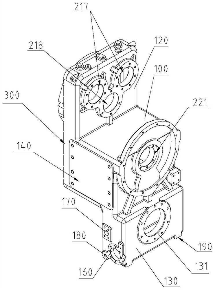
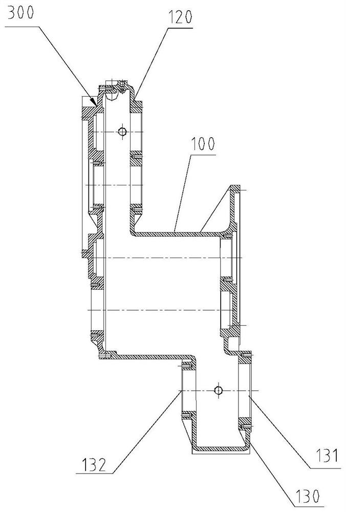
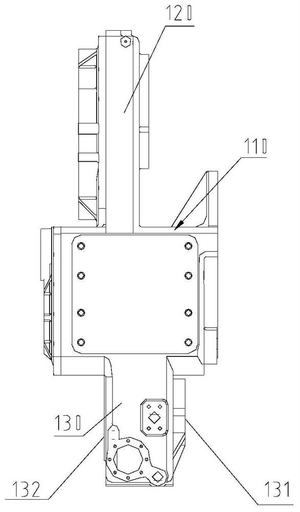
The invention discloses a power box for electric wheel type engineering machinery. The power box comprises a gearbox, a transfer case and a power output box. The transfer case is located on the upper portion of the gearbox. The power output box is located on the lower portion of the gearbox. The gearbox and the transfer case are provided with case covers. Hydraulic pump PTO interfaces and a variable speed pump PTO interface are arranged on the transfer case. A front axle driving interface is formed in one side of the power output box, and a rear axle driving interface is formed in the other side of the power output box. According to the power box, a working device hydraulic pump motor, a running driving motor, the hydraulic pump PTO transfer case, the gearbox, a front output device, a rear output device and the like can be integrated into an integrated power assembly, and a traditional engine, a torque converter and a hydraulic transmission gearbox are directly replaced under the condition that the structure and an oil way of a traditional engineering vehicle are not changed. The power assembly can meet the requirement for independent driving of running of the working device hydraulic pump, a steering pump and the engineering machinery, the motor is adopted for driving, advancing and retreating can be achieved through reverse rotation of the motor, and a reversing mechanism with complex transmission is replaced.
Description
technical field [0001] The invention belongs to electric wheeled construction machinery, in particular to a power box for electric wheeled construction machinery. Background technique [0002] In recent years, various electric vehicle technologies have gradually matured and are reliable, especially the consumption of economical electric vehicle products has been increasing year by year, and the market acceptance has been very impressive. With the regulation and upgrading of environmental protection policies, the country has higher and higher requirements for ecological environment protection, and construction machinery enterprises must also take the initiative in energy conservation and emission reduction to complete industrial upgrading as soon as possible. Especially in some specific working environments such as municipalities, ports, and underground operations, relevant departments have proposed zero-emission thresholds for construction machinery to enter the site. [00...
Claims
Login to View More Application Information
Patent Timeline
 IPC IPC(8): F16H41/24F16H61/40F16H63/30F16H63/34
CPCF16H41/24F16H61/40F16H63/30F16H63/34
Inventor 乔征崔国敏刘艳芳张卫东曹健榕李治江晋佳
Owner TIANJIN ENG MACHINERY INST
Features
- R&D
- Intellectual Property
- Life Sciences
- Materials
- Tech Scout
- Unparalleled Data Quality
- Higher Quality Content
- 60% Fewer Hallucinations
Learn More Browse by: Latest US Patents, China's latest patents, Technical Efficacy Thesaurus, Application Domain, Technology Topic, Popular Technical Reports.
© 2025 PatSnap. All rights reserved.Legal|Privacy policy|Modern Slavery Act Transparency Statement|Sitemap|About US| Contact US: help@patsnap.com


