
Simple tissue holder automatic clip applier

A tissue clip and simple technology, applied in wound clips and other directions, can solve the problems of complex structural design and poor operation stability, and achieve the effect of simple and compact structural design, convenient production, and easy and labor-saving pushing.

Active Publication Date: 2021-07-09
CHANGZHOU CONDINER MEDICAL TECH
View PDF9 Cites 3 Cited by
  • Summary
  • Abstract
  • Description
  • Claims
  • Application Information

AI Technical Summary

Problems solved by technology

[0007] The purpose of the present invention is to overcome the disadvantages of the existing sequential tissue clip applicator such as complex structure design and poor operation stability, and provide a simple tissue clip continuous clip applier. By adopting the technical solution of the present invention, the The clamping action and pushing action of the continuous clamping clamp are divided into two control actions to complete. In the clamp head control mechanism, the design of the storage clamp head is adopted to realize the integrated design of the clamp head and the storage chamber. Move back and forth to make the storage clamp head expand and contract in the clamp rod to drive the first clamp arm and the second clamp arm to open or close; The clips are conveyed forward synchronously; through the cooperative cooperation of the clamp head control mechanism and the push clamp control mechanism, the continuous operation of the clip applicator is realized. Flexible and convenient to use, low production cost

Method used


Image

  • Simple tissue holder automatic clip applier
  • Simple tissue holder automatic clip applier
  • Simple tissue holder automatic clip applier

Examples


Embodiment

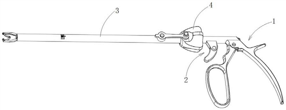
[0049] Such as figure 2 , image 3 , Figure 5 to Figure 7 As shown, a simple type of tissue clip clamp applicator in this embodiment includes a clamp head control mechanism 1, a push clamp control mechanism 2 and a clamp rod 3, and the clamp head control mechanism 1 and push clamp control mechanism 2 are all arranged on On the pincer rod 3, the pincer rod 3 is used to provide the operating length of the pincer head, which is convenient for operation deep into the patient's body. The pincer head control mechanism 1 is used to control the opening or closing of the pincer head, and the push clamp control mechanism 2 is used to realize pushing to the pincer head. tissue clips. in:

[0050] The pincer head control mechanism 1 includes a handle assembly, pincer head push rod 1-4, push rod rack 1-5, transmission gear 1-6 and storage clip pincer head 1-7, and the handle assembly is located at the rear end of the pincer rod 3, The pincer head push rods 1-4 are located inside the ...


PUM


Abstract

The invention discloses a simple tissue holder automatic clip applier, and belongs to the field of clip appliers. The automatic clip applier comprises a clip head control mechanism, a clip pushing control mechanism and a clip rod, the clip head control mechanism comprises a handle assembly, a clip head push rod, a push rod rack, a transmission gear and a clip storage clip head, and the clip pushing control mechanism comprises a clip pushing operation handle, a clip feeding push rod, a clip storage bin clip piece and a clip feeding push piece. The clamping closing action and the clip pushing action of the automatic clip applier are completed through two control actions, the clip storage head design is adopted to achieve the integrated design of the clip head and the clip storage bin, and the clip storage head moves back and forth to enable the clip storage head to stretch out and draw back in the clip rod to drive the two clip head arms to be opened or closed; the tissue holder in the clip storage head are synchronously and forwards conveyed by adopting the clip conveying push sheet; through cooperation of the clip head control mechanism and the clip pushing control mechanism, automatic operation of the clip applier is achieved, and the clip applier is simple and compact in structural design, stable and reliable in clip pushing and closing operation, flexible and convenient to use and low in manufacturing cost.

Description

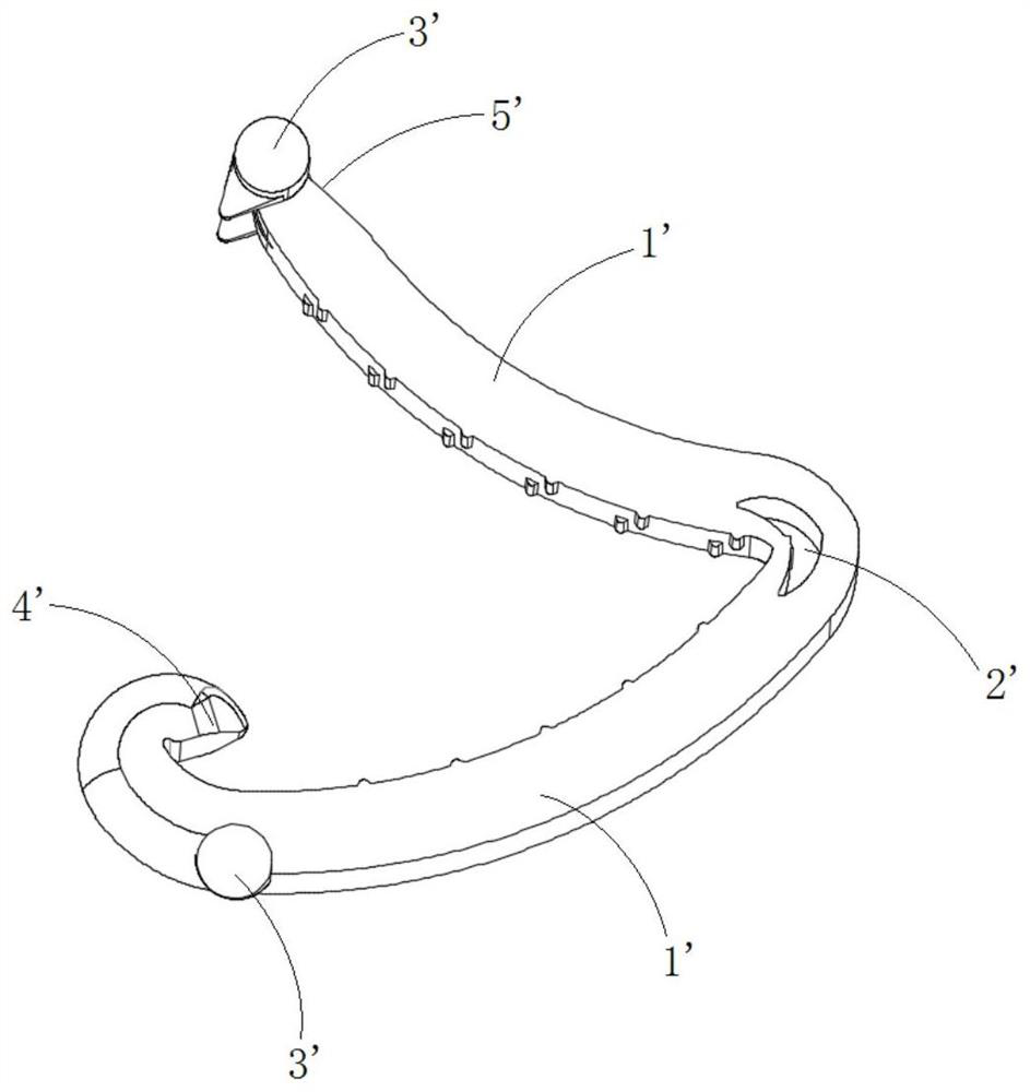
technical field [0001] The invention relates to a medical clip applier, in particular to a simple tissue clip continuous hair clip applier. Background technique [0002] Tissue clip is a new type of surgical instrument that has been widely adopted by medical institutions all over the world in the past ten years. It is mainly used to close or ligate tubular tissues, such as blood vessels and bile ducts, in minimally invasive surgery. Such as figure 1 As shown, it is mainly composed of two clamp arms 1', the two clamp arms 1' are connected by the rotating part 2' to form a roughly "V"-shaped clamp body, and a clasp is provided at the end of one clamp arm 1' 4', the end of the other clamp arm 1' is provided with a buckle groove 5', when the tissue clip is closed, the clasp 4' is buckled into the buckle groove 5' to realize the stable closure of the tissue clip. [0003] Clip applier is a commonly used instrument for closing the above-mentioned tissue clips. It mainly uses the...

Claims


Application Information

Patent Timeline
IPC IPC(8): A61B17/128
CPCA61B17/1285
Inventor 严海露彭超查一峰徐爱英许丹
Owner CHANGZHOU CONDINER MEDICAL TECH
Learn More