Supercharge Your Innovation With Domain-Expert AI Agents!

A kind of raw material cutting equipment for new energy vehicle circuit board

A new energy vehicle and cutting equipment technology, applied in the field of new energy vehicle circuit board raw material cutting equipment, can solve the problems of high use limitation and poor cutting effect, etc.

Active Publication Date: 2022-07-08
江西威尔高电子股份有限公司
View PDF12 Cites 0 Cited by
  • Summary
  • Abstract
  • Description
  • Claims
  • Application Information

AI Technical Summary

Problems solved by technology

[0004] In order to overcome the disadvantages of the existing cutting device, such as high limitation of use and poor cutting effect, the purpose of the present invention is to provide a cutting device for raw materials of circuit boards of new energy vehicles that can realize automatic fixing and good cutting effect

Method used


Image

  • A kind of raw material cutting equipment for new energy vehicle circuit board
  • A kind of raw material cutting equipment for new energy vehicle circuit board
  • A kind of raw material cutting equipment for new energy vehicle circuit board

Examples


Embodiment 1

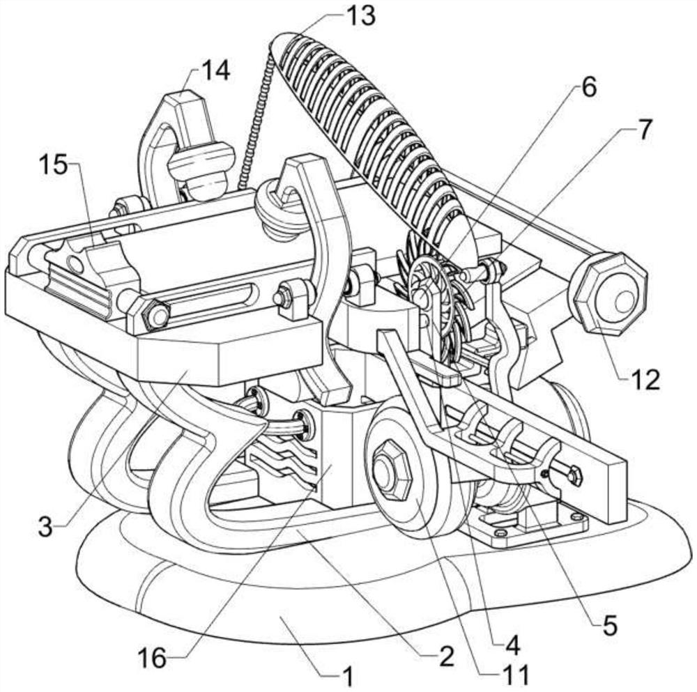
[0028] A raw material cutting equipment for circuit boards of new energy vehicles, such as Figure 1-5 As shown, it includes a bottom plate 1, a bracket 2, a first mounting plate 3, a first guide rod 4, a first connecting plate 5, a brushless motor 6, a cutter 7, a first connecting frame 8, a first rotating shaft 9, a first Two mounting plates 10, a power mechanism 11 and a residual material removal mechanism 12, two brackets 2 are arranged on the rear side of the bottom plate 1, a first mounting plate 3 is arranged between the tops of the brackets 2, and the right side of the first mounting plate 3 is slidably connected with a The first guide rod 4, the right side of the first guide rod 4 is provided with a first connecting plate 5, the first connecting plate 5 is provided with a brushless motor 6, the output shaft of the brushless motor 6 is connected with a cutter 7, and the first mounting plate 3. The right part of the rear side is provided with a first connecting frame 8,...

Embodiment 2

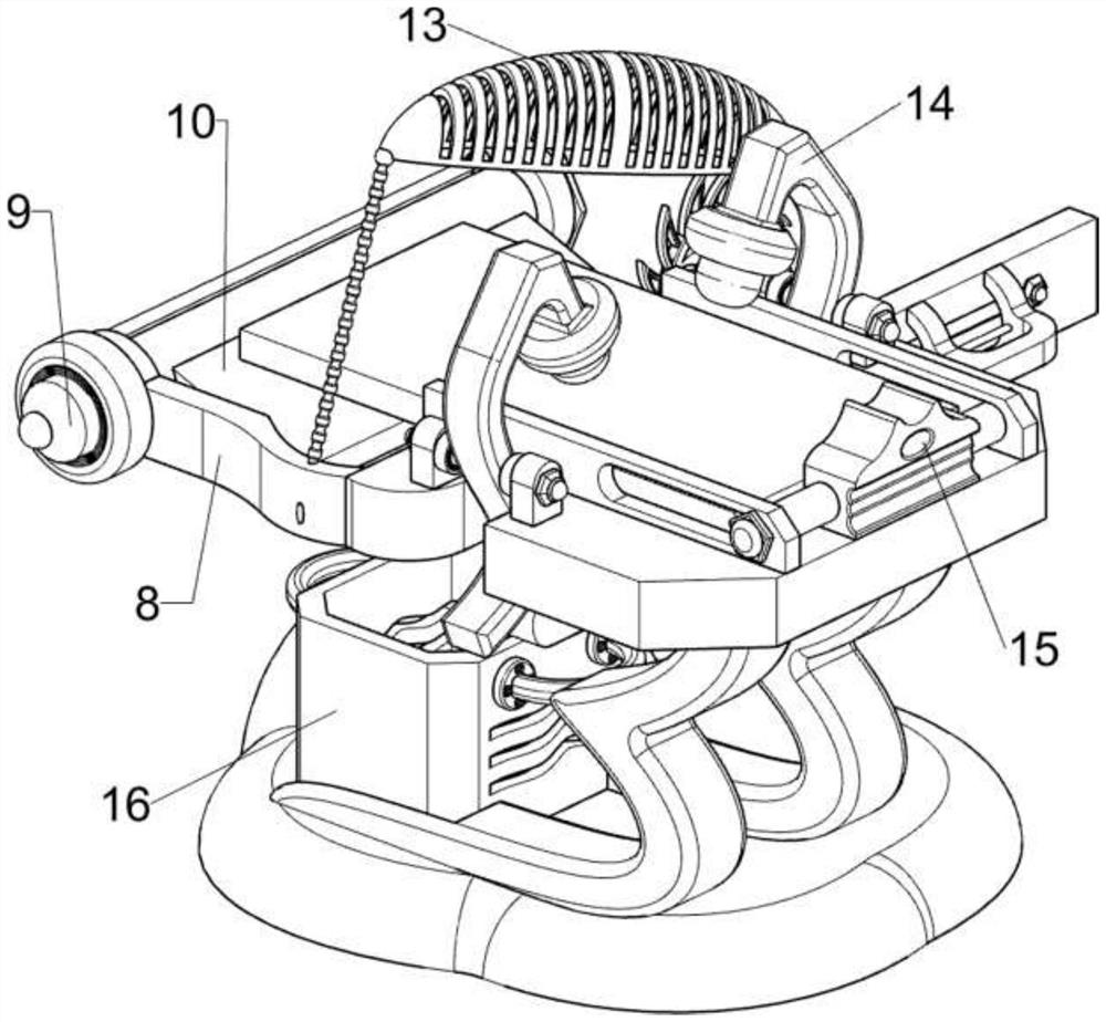
[0033] On the basis of Example 1, as Figure 6-10 As shown, a protection mechanism 13 is also included, and the protection mechanism 13 includes a first bearing seat 130, a second bearing seat 131, a reel 132, a traction wire 133, a third rotating shaft 134, a second scroll spring 135 and a protective cover 136. A first bearing seat 130 is provided on the right rear side of the guide rail 111, a second bearing seat 131 is provided on the lower side of the rear part of the first bearing seat 130, and a reel 132 is rotatably connected to the second bearing seat 131. The second bearing seat The upper part of 131 is rotatably connected with a third rotating shaft 134, a second scroll spring 135 is connected between the third rotating shaft 134 and the second bearing seat 131, and a pulling wire 133 is arranged on the lower right side of the first connecting plate 5, and the pulling wire 133 is wound around Passing through the reel 132 , the pulling wire 133 passes through the firs...


PUM


Abstract

The invention relates to a cutting device, in particular to a raw material cutting device for a circuit board of a new energy vehicle. The purpose of the present invention is to provide a raw material cutting device for new energy vehicle circuit boards that can realize automatic fixing and good cutting effect. The technical scheme is as follows: a raw material cutting equipment for circuit boards of new energy vehicles, comprising a bottom plate, a bracket, a first mounting plate, a first guide rod and a first connecting plate, two brackets are arranged on one side of the bottom plate, and the top of the bracket is provided with two brackets. A first mounting plate is arranged therebetween, one side of the first mounting plate is slidably connected with a first guide rod, and one side of the first guide rod is provided with a first connecting plate. Through the cooperation between the power mechanism and the residual material removal mechanism, the effect of automatically supporting the raw material of the new energy vehicle circuit board and automatically cutting the raw material of the new energy vehicle circuit board can be realized.

Description

technical field [0001] The invention relates to a cutting device, in particular to a raw material cutting device for a circuit board of a new energy vehicle. Background technique [0002] The cutting device for the production of raw materials of automobile circuit boards is an auxiliary device used for cutting the raw materials of automobile circuit boards in the production process of raw materials of automobile circuit boards, so that the raw materials of automobile circuit boards can be better completed and worked. It is widely used in the field of component production. [0003] It is found in the existing cutting devices for the production of raw materials of automobile circuit boards that they cannot be fixed according to the size of the raw materials of automobile circuit boards, and the use limitations are high and the cutting effect is poor. The automatic fixing and cutting effect is good for the new energy vehicle circuit board raw material cutting equipment. SUMM...

Claims


Application Information

Patent Timeline
Patent Type & Authority Patents(China)
IPC IPC(8): B23D47/04B23D47/02B23D47/12B23D59/00B23Q7/06B23Q7/10B23Q11/08
CPCB23D47/04B23D47/02B23D47/12B23D59/00B23Q7/06B23Q7/10B23Q11/08
Inventor 邓艳群罗太重陈晓东樊本军
Owner 江西威尔高电子股份有限公司
Features
  • R&D
  • Intellectual Property
  • Life Sciences
  • Materials
  • Tech Scout
  • Unparalleled Data Quality
  • Higher Quality Content
  • 60% Fewer Hallucinations
Learn More