Design method of high-performance imaging system

A technology of imaging system and design method, applied in the field of visual imaging

Active Publication Date: 2021-07-09
BEIJING LUSTER LIGHTTECH
View PDF3 Cites 0 Cited by
  • Summary
  • Abstract
  • Description
  • Claims
  • Application Information

AI Technical Summary

Problems solved by technology

[0005] This application provides a design method of a high-performance imaging system to solve the problem of how to determine a more matching image sensor and lens, and take into account cost performance and data bandwidth

Method used


Image

  • Design method of high-performance imaging system
  • Design method of high-performance imaging system
  • Design method of high-performance imaging system

Examples


Embodiment 1

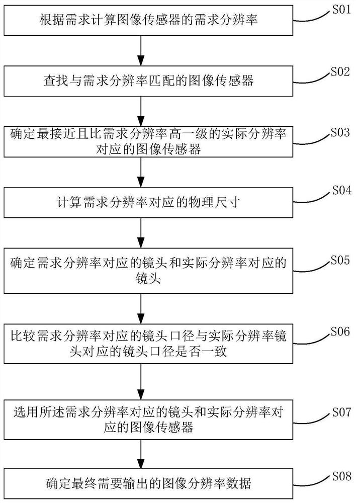
[0044] Such as figure 2 As shown, the design method of a high-performance imaging system provided by the application includes the following steps:

[0045] S01: Calculate the required resolution of the required image sensor according to the application requirements;

[0046] In this embodiment, the application requirements include: the required detection accuracy of the image sensor and the field of view of the camera.

[0047] Specifically: the application requirements include the application requirements of line array cameras and the application requirements of area array cameras;

[0048] Then, for the line array camera, the application requirements of the line array camera include: the detection accuracy of the required image sensor corresponding to the line array camera and the horizontal field of view width of the line array camera, the field of view of the line array camera is represented by the image of the line array camera The long side of the sensor shall prevail...

Embodiment 2

[0083] Different from Embodiment 1, Embodiment 2 includes the following steps:

[0084] S01: Calculate the required resolution of the required image sensor according to the application requirements;

[0085] S02: Find an image sensor that matches the required resolution;

[0086] S03: If there is an image sensor matching the required resolution, select an image sensor matching the required resolution;

[0087] S04: Obtain the physical size corresponding to the required resolution;

[0088] S05: Determine the lens corresponding to the required resolution according to the physical size corresponding to the required resolution.

Embodiment 3

[0090] Different from Embodiment 1 and Embodiment 2, Embodiment 3 includes the following steps:

[0091] S01: Calculate the required resolution of the required image sensor according to the application requirements;

[0092] S02: Find an image sensor that matches the required resolution;

[0093] S03: If there is no image sensor matching the required resolution, determine the image sensor corresponding to the actual resolution that is closest and one level higher than the required resolution;

[0094] S04: Calculate the physical size corresponding to the required resolution according to the required resolution, the actual resolution, and the physical size corresponding to the actual resolution;

[0095] S05: Determine the lens corresponding to the required resolution and the lens corresponding to the actual resolution according to the physical size corresponding to the required resolution and the physical size corresponding to the actual resolution;

[0096] S06: Compare whe...


PUM


Abstract

The invention relates to a design method of a high-performance imaging system. The design method comprises the following steps: calculating a required resolution required to be met by an image sensor according to application requirements; searching an image sensor matched with the required resolution; if not, determining the image sensor corresponding to the actual resolution which is closest to the required resolution and is one level higher than the required resolution; calculating the physical size corresponding to the required resolution according to the required resolution, the actual resolution and the physical size corresponding to the actual resolution; determining a lens corresponding to the required resolution and a lens corresponding to the actual resolution according to the physical size corresponding to the required resolution and the physical size corresponding to the actual resolution; comparing whether the lens apertures are consistent or not; and if the lens aperture corresponding to the actual resolution is greater than the lens aperture corresponding to the required resolution, selecting a lens corresponding to the required resolution and an image sensor corresponding to the actual resolution. According to the invention, high-performance requirement of the imaging system can be met, and the processing amount of the imaging system can be effectively reduced.

Description

technical field [0001] The present application relates to the field of visual imaging technology, in particular to a design method of a high-performance imaging system. Background technique [0002] The imaging system in industrial vision mainly includes camera, lens, acquisition card (optional), light source, and power supply. Among them, the camera is the core device of the imaging system, and its performance is mainly determined by the image sensor. The resolution, pixel size, and circuit design of the image sensor will determine the size of the image sensor, and the size of the image sensor will affect the selection of the lens. Usually, in order to make full use of the full resolution of the image sensor and for better image quality, a lens with an aperture larger than the target surface size of the image sensor is selected, such as figure 1 As shown, the lens aperture indicates the maximum light entrance of the lens, that is, the maximum aperture of the lens. [0003...

Claims


Application Information

Patent Timeline
IPC IPC(8): H04N5/225
CPCH04N23/54H04N23/55H04N23/45
Inventor 郭慧张延申王艺
Owner BEIJING LUSTER LIGHTTECH
Why Eureka
Try Eureka