Electrical cabinet

A technology of electrical cabinets and outer boxes, applied in the field of electrical cabinets, can solve the problems of waste of resources, occupying space in electrical cabinets, and many fans, and achieve the effect of improving the effect of dust removal and space utilization

Active Publication Date: 2021-07-09
WUHAN MARINE MACHINERY PLANT
View PDF10 Cites 1 Cited by
  • Summary
  • Abstract
  • Description
  • Claims
  • Application Information

AI Technical Summary

Problems solved by technology

[0004] However, since the dust removal electric fan can only be aimed at one direction for blowing, the electrical components located in other directions of the electrical cabinet cannot be dust removed.
However, if the number of dust-removing electric fans is increased to blow other directions, there will be too many fans, resulting in waste of resources and taking up a large space in the electrical cabinet.

Method used


Image

  • Electrical cabinet
  • Electrical cabinet
  • Electrical cabinet

Examples


Embodiment Construction

[0053] In order to make the purpose, technical solution and advantages of the present disclosure clearer, the implementation manners of the present disclosure will be further described in detail below in conjunction with the accompanying drawings.

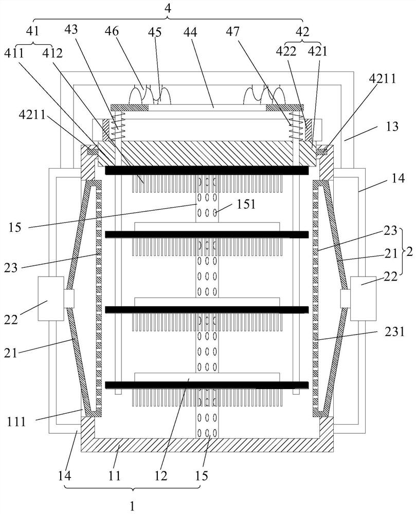
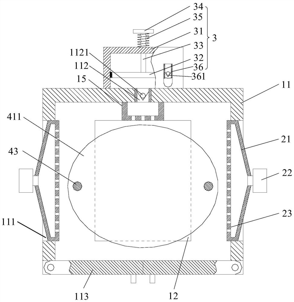
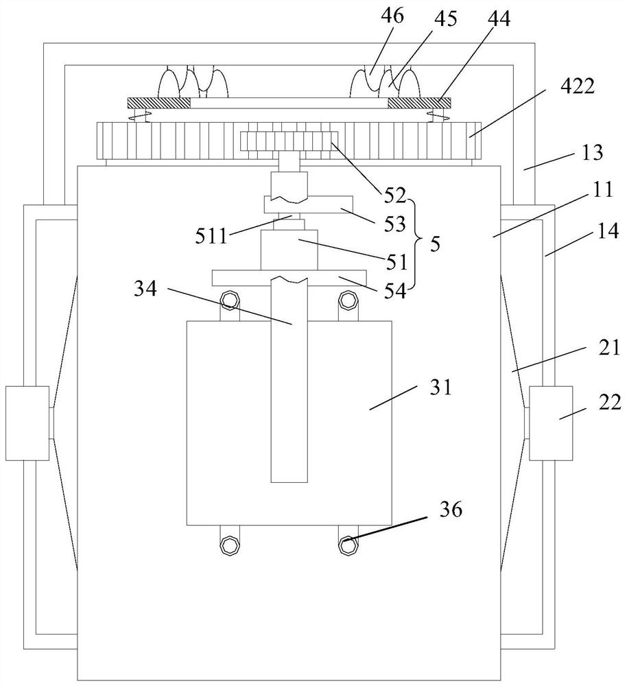
[0054] An embodiment of the present disclosure provides an electrical cabinet, such as figure 1 As shown, the electrical cabinet includes a box body 1 , a blower assembly 2 , an air pump 3 , a cleaning assembly 4 and a drive assembly 5 . The box body 1 includes an outer box 11 and a plurality of mounting plates 12. The side wall of the outer box 11 has an air inlet 111 and an air outlet 112. The air inlet 111 and the air outlet 112 are respectively located on different side walls of the outer box 11. Multiple mounting plates 12 is connected to the inner side wall of the outer box 11, and a plurality of mounting plates 12 are arranged at intervals along the vertical direction. The blowing assembly 2 is located in the air inlet 111 an...


PUM


Abstract

The invention provides an electrical cabinet, belonging to the technical field of power equipment. The electrical cabinet comprises a box body, an air blowing assembly, an air draft pump, a cleaning assembly and a driving assembly, wherein the box body comprises an outer box and a plurality of mounting plates; an air inlet and an air outlet are formed in the side wall of the outer box; the air blowing assembly is located in the air inlet and connected with the side wall of the box body; the air outlet of the air blowing assembly communicates with the interior of the box body; the air draft pump is located at the air outlet and connected with the side wall of the box body; the cleaning assembly comprises a plurality of brushes, the brushes and the plurality of mounting plates are arranged in a one-to-one correspondence mode, the brushes are rotatably located in the outer box and located above the corresponding mounting plates, and the rotating axes of the brushes are perpendicular to the mounting plates; the driving assembly is connected with the outer side wall of the outer box, and the driving assembly is used for driving the air draft pump to extract air in the outer box and driving the multiple brushes to rotate. The electrical cabinet can efficiently remove dust on electrical elements.

Description

technical field [0001] The disclosure belongs to the technical field of electric equipment, and in particular relates to an electric cabinet. Background technique [0002] Electrical cabinets are processed from steel to accommodate electrical components, and are widely used in various industries. Because there are holes for heat dissipation on the electrical cabinet, a large amount of dust will accumulate on the surface of the electrical components in the electrical cabinet as time goes by, and if the dust accumulates for a long time and is not cleaned, it will affect the normal operation of the electrical components. Therefore, it is necessary to regularly remove dust from the electrical components inside the electrical cabinet. [0003] In the related art, generally, a dust removal fan is arranged inside the electrical cabinet, and the surface of the electrical components in the electrical cabinet is blown by the dust removal fan, so as to achieve the purpose of dust remo...

Claims


Application Information

Patent Timeline
Patent Type & Authority Applications(China)
IPC IPC(8): H05K5/00H05K5/02H05K5/04B08B1/00B08B1/04
CPCH05K5/0004H05K5/04H05K5/0217H05K5/0247B08B1/002B08B1/04
Inventor 万志辉黄浩张文亮熊欣
Owner WUHAN MARINE MACHINERY PLANT
Why Eureka
Try Eureka