Eureka AIR delivers breakthrough ideas for toughest innovation challenges, trusted by R&D personnel around the world.

Computerized embroidery machine with dynamic keeping mechanism and working method of computerized embroidery machine

A technology for maintaining mechanisms and embroidery machines, which is applied to the mechanism of embroidery machines, embroidery machines, textiles and papermaking, etc. It can solve the problems of lower embroidery pattern quality, complex structure, and lower quality, so as to improve the success rate of stitching and knotting, Improve embroidery efficiency and simple structure

Pending Publication Date: 2021-07-13
ZHEJIANG YUELONG SEWING EQUIP
View PDF0 Cites 0 Cited by
  • Summary
  • Abstract
  • Description
  • Claims
  • Application Information

AI Technical Summary

Problems solved by technology

However, the embroidery action of the existing embroidery machine has the following defects: 1. If the length of the upper thread is not enough or the tension is not enough during embroidery, it is easy to appear that the first stitch embroidery is not in place, and it is easy to lose the bottom thread, which will cause the upper thread and the bottom thread to fail. A knotted state will eventually lead to a reduction in the quality of the embroidery pattern; 2. Inadequate starting of the embroidery machine will result in missed stitches or a few stitches before the bottom thread can be picked up, which will lead to reduced efficiency and reduced quality
However, this embroidery machine needs to set a special electromagnet as a driving mechanism to drive the thread-catching spring to catch the upper thread, which has a complex structure and requires additional driving costs.

Method used


Image

  • Computerized embroidery machine with dynamic keeping mechanism and working method of computerized embroidery machine
  • Computerized embroidery machine with dynamic keeping mechanism and working method of computerized embroidery machine
  • Computerized embroidery machine with dynamic keeping mechanism and working method of computerized embroidery machine

Examples


Embodiment Construction

[0035] The technical solution in the present invention will be clearly and completely described below in conjunction with the accompanying drawings in the present invention. Obviously, the described embodiments are part of the embodiments of the present invention, not all of them. Based on the embodiments of the present invention, all other embodiments obtained by persons of ordinary skill in the art without making creative efforts shall fall within the protection scope of the present invention.

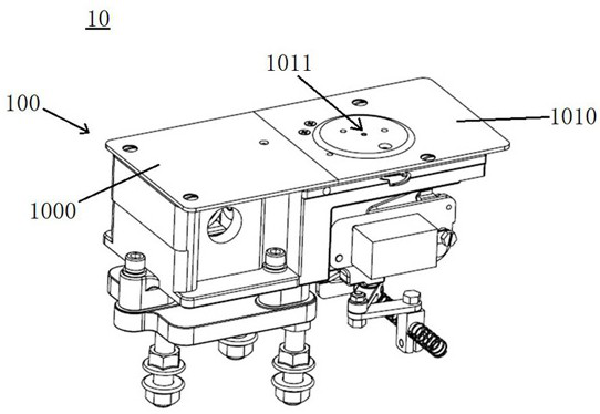
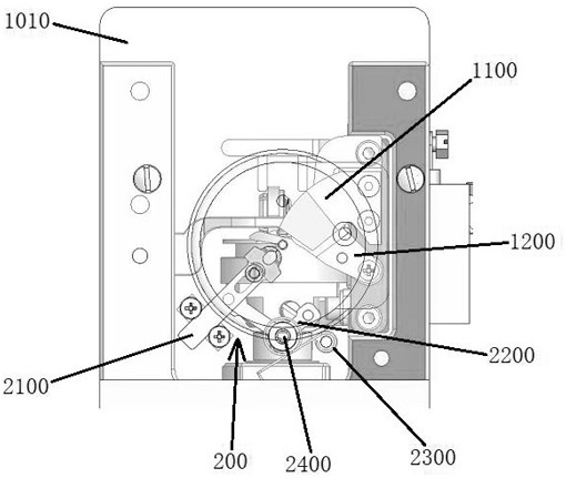
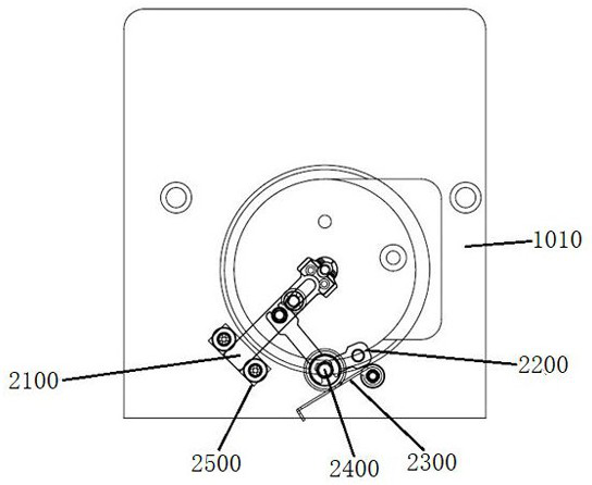
[0036] Such as Figure 1-5 As shown, the embodiment of the present invention provides a computerized embroidery machine 10 with a dynamic holding mechanism, including: a shuttle box part 100 and a dynamic holding mechanism 200 . The computerized embroidery machine 10 also includes other mechanisms (not shown in the figure), such as the head of the embroidery machine, etc. The head of the embroidery machine controls the movement of the embroidery needle, and the prior art in this fiel...


PUM


Abstract

The invention discloses a computerized embroidery machine with a dynamic keeping mechanism and a working method of the computerized embroidery machine, and relates to the technical field of computerized embroidery machines. The computerized embroidery machine comprises a shuttle box body component and the dynamic keeping mechanism; the shuttle box body component comprises a shuttle box with a needle plate, a fixed cutter and a movable cutter, wherein the fixed cutter and the movable cutter are arranged in the shuttle box; a needle plate hole is formed in the needle plate; the dynamic keeping mechanism is arranged in the shuttle box and comprises a keeping piece located on the back side of the needle plate, and a shifting piece, a torsional spring and a mounting pin; the mounting pin is fixedly connected to the back face of the needle plate; the shifting piece is rotatably arranged on the mounting pin in a sleeving mode; the torsional spring is arranged between the needle plate and the shifting piece to provide restoring force for the shifting piece, and the shifting piece is connected with the keeping piece; a central hole is formed in one end of the keeping piece; and when the movable cutter is opened relative to the fixed cutter, the movable cutter drives the shifting piece to rotate around the mounting pin, and meanwhile the shifting piece drives the keeping piece to linearly move towards the needle plate hole till the central hole is aligned with the needle plate hole. The embroidery quality and efficiency of the embroidery machine can be improved, the structure of the embroidery machine is simplified, and the cost is reduced.

Description

technical field [0001] The invention relates to the technical field of computerized embroidery machines, and more specifically, to a computerized embroidery machine with a dynamic holding mechanism and its working method. Background technique [0002] The working principle of the computerized embroidery machine is that the upper thread and the lower thread work together, and finally the embroidery pattern is drawn on the fabric. At present, when the embroidery machine starts to embroider, it needs to bring the embroidery upper thread into the shuttle box through the needle, and the rotary hook separates the upper thread and cooperates with the bottom thread to tie a knot, and finally realizes the embroidery action. However, the embroidery action of the existing embroidery machine has the following defects: 1. If the length of the upper thread is not enough or the tension is not enough during embroidery, it is easy to appear that the first stitch embroidery is not in place, a...

Claims


Application Information

Patent Timeline
Patent Type & Authority Applications(China)
IPC IPC(8): D05C11/00D05C11/20
CPCD05C11/00D05C11/20
Inventor 陈天池张汉苗郑邓飞楼凯赵泽
Owner ZHEJIANG YUELONG SEWING EQUIP
Why Eureka
Eureka Blog
Learn More