
Rope winding mechanism of novel soft rope knotter

A knotter and soft rope technology, which is applied in the field of knotting machines, can solve the problems of easy falling off of the cord, high knotting success rate, and easy fixing of the cord, etc., to improve the knotting success rate, reduce vibration, and reduce gaps Effect

Pending Publication Date: 2022-07-29
ZHENGZHOU XIELI CONSTR EQUIP
View PDF0 Cites 0 Cited by
  • Summary
  • Abstract
  • Description
  • Claims
  • Application Information

AI Technical Summary

Problems solved by technology

[0005] Aiming at the deficiencies of the prior art, the present invention provides a new type of rope winding mechanism for a soft rope knotter, which has the advantages of high knotting success rate, easy fixing of the cord, etc., and solves the problem that the cord is easy to fall off

Method used


Image

  • Rope winding mechanism of novel soft rope knotter
  • Rope winding mechanism of novel soft rope knotter
  • Rope winding mechanism of novel soft rope knotter

Examples


Embodiment 1

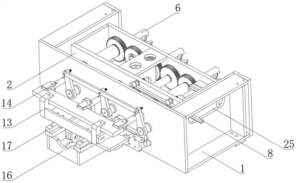
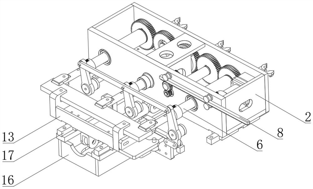
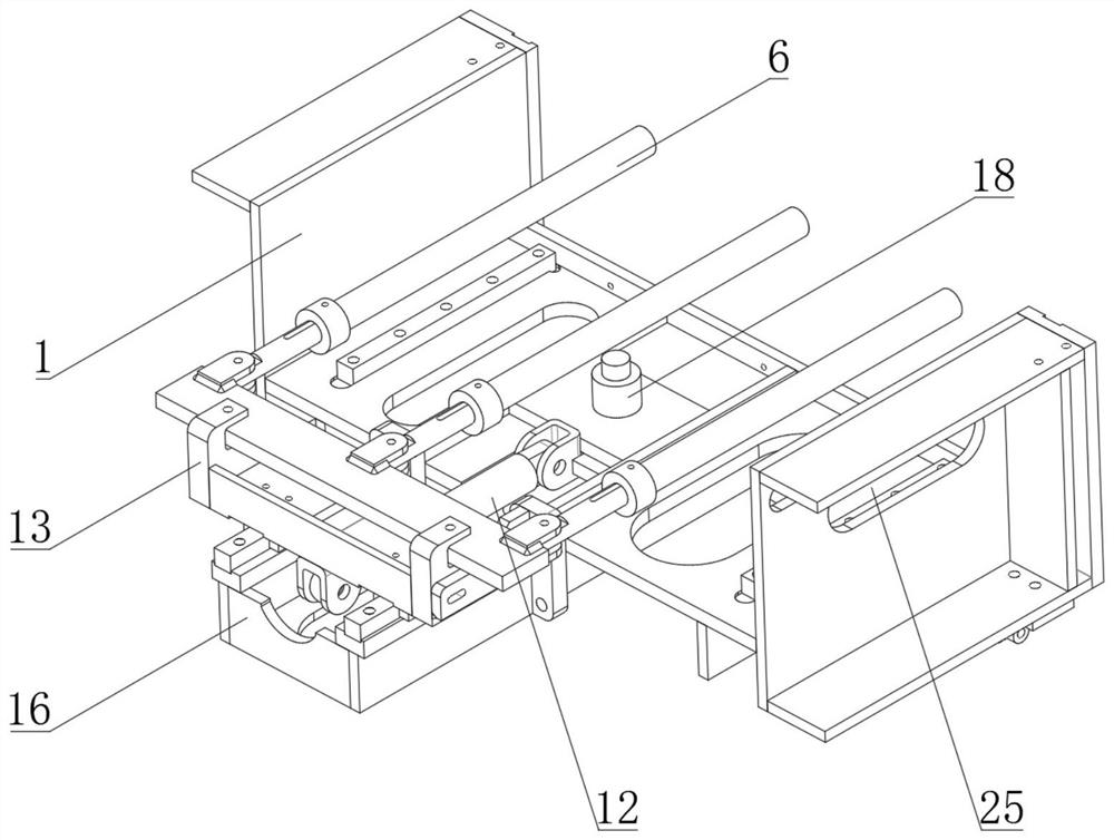
[0033] see Figure 1-9 , a new type of rope winding mechanism for a soft rope knotter, comprising a casing 1, the inner wall of the casing 1 is connected with a sliding frame 2 through a track, a rotating drum 3 is installed inside the sliding frame 2, and the outer surface of the rotating drum 3 is provided with a spiral Slot 4, a drive gear 5 is detachably connected to one side of the drum 3, a drive mechanism is provided on the back of the sliding frame 2, a support drum 6 is fixedly connected to the back of the shell 1, a pulling mechanism is installed at the bottom of the shell 1, and the drum 3 A fixing mechanism is provided near one end of the driving gear 5 .

[0034] In this embodiment, the sliding frame 2 can slide in the casing 1. After the fixing mechanism clamps the wire rope, the rotation of the rotating drum 3 will drive the fixing mechanism at one end of the rotating drum 3 to rotate, thereby winding the wire rope on the fixing mechanism. The rope operation, a...

Embodiment 2

[0036] According to Embodiment 1, the driving mechanism includes a guide wheel 7 mounted on the back of the sliding frame 2, the inner wall of the guiding wheel 7 is provided with a rack 8, one side of the back of the sliding frame 2 is provided with a connecting wheel 9, and one side of the driving gear 5 is engaged with There is a reversing gear 10, and the inner wall of the reversing gear 10 is connected with a connecting rod 11 through a keyway.

[0037] In this embodiment, the guide wheel 7 pushes the rack 8 against the connecting wheel 9 to ensure that the rack 8 and the connecting wheel 9 fit together, and a reversing gear 10 is arranged between the two driving gears 5 to ensure that each driving The rotation direction between the gears 5 is the same, which is more neat in the process of knotting.

Embodiment 3

[0039] According to Embodiment 2, both the lower surface of the rack 8 and the end of the connecting rod 11 away from the reversing gear 10 are engaged with the outer surface of the connecting wheel 9 .

[0040] In this embodiment, when the connecting rod 11 rotates, the connecting rod 11 will drive the connecting wheel 9 to rotate together, thereby driving the rack 8 to move left and right. The position of the connecting rod 11 is positioned to determine the rotation angle of the connecting rod 11, and the rotation is driven by the hydraulic motor on the side.


PUM


Abstract

The novel rope winding mechanism of the soft rope knotter comprises a shell, the inner wall of the shell is connected with a sliding frame through a rail, a rotating drum is installed in the sliding frame, a spiral groove is formed in the outer surface of the rotating drum, one side of the rotating drum is detachably connected with a driving gear, and the driving gear is connected with a driving motor. A driving mechanism is arranged on the back face of the sliding frame, a supporting cylinder is fixedly connected to the back face of the shell, and a pulling mechanism is installed at the bottom of the shell. According to the rope winding mechanism of the novel soft rope knotter, through matched arrangement of the rotating cylinder, the spiral groove and the limiting block, when the rotating cylinder rotates, the limiting block can abut against the interior of the spiral groove, the rotating cylinder moves front and back, through matched arrangement of the pull rod, the supporting cylinder and the pull rod, knotting can be divided into rope winding operation and rope hooking operation, and the knotting efficiency is improved. Through cooperative arrangement of the baffle, the pressing plate and the torsional spring, in the knotting process, the torsional spring can push the pressing plate, so that the pressing plate is pressed on the baffle, and the position of the rope is fixed.

Description

technical field [0001] The invention relates to the technical field of knotting machines, in particular to a rope winding mechanism of a novel soft rope knotter. Background technique [0002] The waste paper baler is used to squeeze the waste paper and similar products firmly under normal conditions, and pack them with special packaging tapes to greatly reduce the volume. For tying up waste paper, the knotter is a machine used to tie the cords. Compared with the manual bundling of workers, the knotter reduces the difficulty of operation and reduces the physical burden of workers. [0003] Most of the existing knotting machines use hooks to hook the rope for rotation, but the rope easily falls off the hook during the rotation, resulting in the failure of knotting, which requires a device to solve the above problem. SUMMARY OF THE INVENTION [0004] (1) Technical problems solved [0005] Aiming at the deficiencies of the prior art, the present invention provides a new rope...

Claims


Application Information

Patent Timeline
Patent Type & Authority Applications(China)
IPC IPC(8): B65B13/26
CPCB65B13/26
Inventor 张国宾
Owner ZHENGZHOU XIELI CONSTR EQUIP
Learn More