Method for producing zip fastener

A manufacturing method and zipper technology, applied in the field of zipper manufacturing, can solve the problems of pin and fixed pin falling off, positioning error, influence, etc.

Inactive Publication Date: 2004-05-26
GENMORE ZIPPER CORP
View PDF0 Cites 0 Cited by
  • Summary
  • Abstract
  • Description
  • Claims
  • Application Information

AI Technical Summary

Problems solved by technology

[0010] In the traditional zipper manufacturing process, because the patch 4A is the yarn core 11A, 22A that covers the end edges of the tapes 1A, 2A, the inserting tip and the fixing tip will be directly injection-molded on the patch 4A. When 4A falls off from the cloth tapes 1A and 2A, it will cause the plugging and fixing pins to fall off; in addition, when the clot

Method used


Image

  • Method for producing zip fastener
  • Method for producing zip fastener
  • Method for producing zip fastener

Examples


Embodiment Construction

[0029] The detailed description and technical content of the present invention are as follows in conjunction with the accompanying drawings:

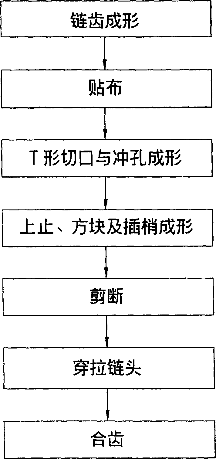
[0030] The present invention is a "manufacturing method of zipper", please refer to Figure 4 Shown is the flow chart of the slide fastener forming steps of the present invention, and the forming steps are as follows:

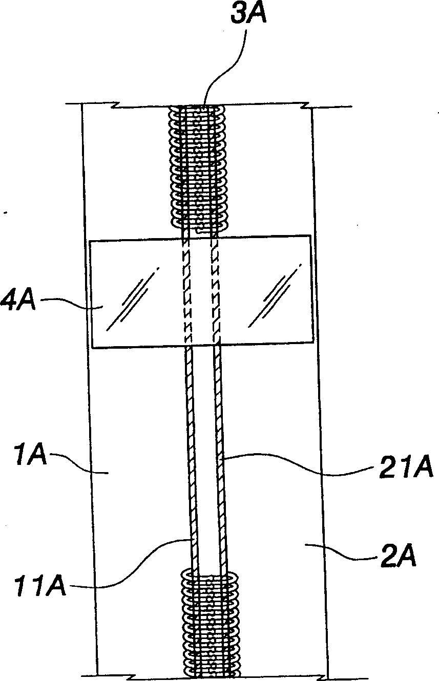
[0031] (A) sprocket forming or timing forming, the cloth tapes 1 and 2 are first input into the injection molding machine, so that the cloth tapes 1 and 2 are injection-molded with sprocket 3;

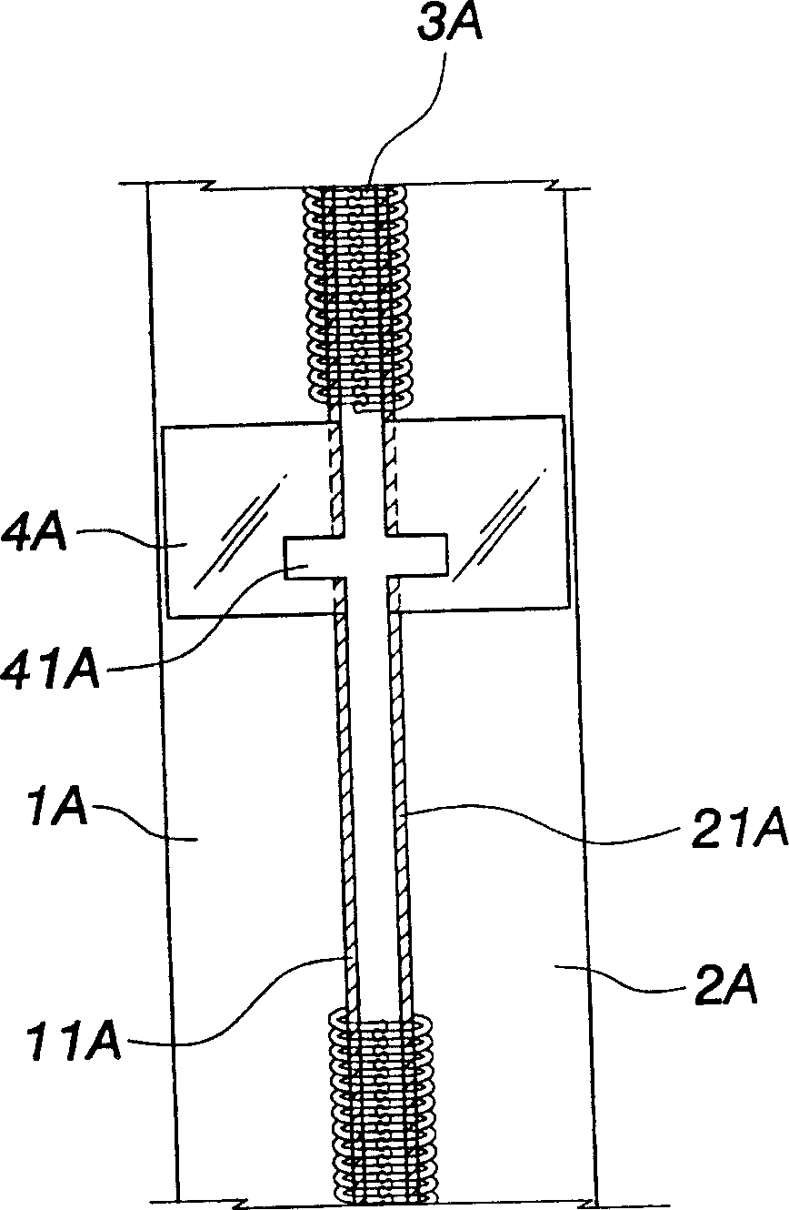
[0032] (B) patch and elongated slit: a patch 4 is respectively fixed at the upper and lower positions of the insert pin 63 and the solid tip 64 on the cloth tapes 1 and 2, and a long patch 4 is punched on the patch 4. Shaped slit 41, the elongated slit 41 does not cover the yarn core 11, 21 (cord) on both sides of the cloth tape 1, 2, and an auxiliary flow channel for ultrasonic trimming is provided at the appropriate position o...


PUM


Abstract

A technology for manufacturing zipper includes forming teeth of zipper, providing fabric belt with cord at edge, radially cutting, punching holes, ejection moulding of upper stops, plug pins and fixed pins while directly fixing them on said cords, inserting its start end, engaging the teeth, fixing lower stop block, and cutting short by needed size. Its advantage is high positioning accuracy.

Description

technical field [0001] The invention relates to a manufacturing method of a zipper, especially to a zipper in the manufacturing process, so that the injection-molded inserting pin and fixing pin can be directly formed on the yarn core at the end edge of the cloth tape, so as to prevent the forming from sticking The cloth will fall off when it is on the cloth, and a positioning device is used to prevent the cloth belt from deflecting when it is moved forward and formed, and to eliminate the positioning error caused by the stretchability of the chain belt itself. Background technique [0002] The traditional zipper manufacturing steps are as follows, such as figure 1 shown. [0003] (A) sprocket injection molding or timing molding, the tapes 1A, 2A are input into the injection molding machine, so that the top of the cloth tapes 1A, 2A is injection-molded with the sprocket 3A and the top stop; [0004] (B) Patch: A patch 4A is fixed at the predetermined position above and bel...

Claims


Application Information

Patent Timeline
IPC IPC(8): B29C45/14B29D5/00
Inventor 王联洲
Owner GENMORE ZIPPER CORP
Why Eureka
Try Eureka