High-voltage camera shooting metering device

A metering device, high-voltage technology, applied in the direction of measuring devices, image communication, instruments, etc., can solve the problems of inability to ensure the stability of the device, inconvenient movement, and reduce the use efficiency of the device, so as to ensure the device, improve the use efficiency, and facilitate the use Effect

Pending Publication Date: 2021-07-13
JIANGSU TUOCHUANG SCI INSTR CO LTD
View PDF10 Cites 0 Cited by
  • Summary
  • Abstract
  • Description
  • Claims
  • Application Information

AI Technical Summary

Problems solved by technology

[0004] The purpose of the present invention is to solve the shortcomings that the device is inconvenient to move during use, or the stability of the device cannot be ensured during use when it can be moved, and the use efficiency of the device is reduced to a certain extent, and the proposed high-voltage camera measurement device

Method used


Image

  • High-voltage camera shooting metering device
  • High-voltage camera shooting metering device
  • High-voltage camera shooting metering device

Examples


Embodiment 1

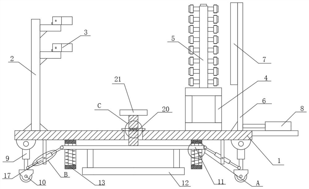
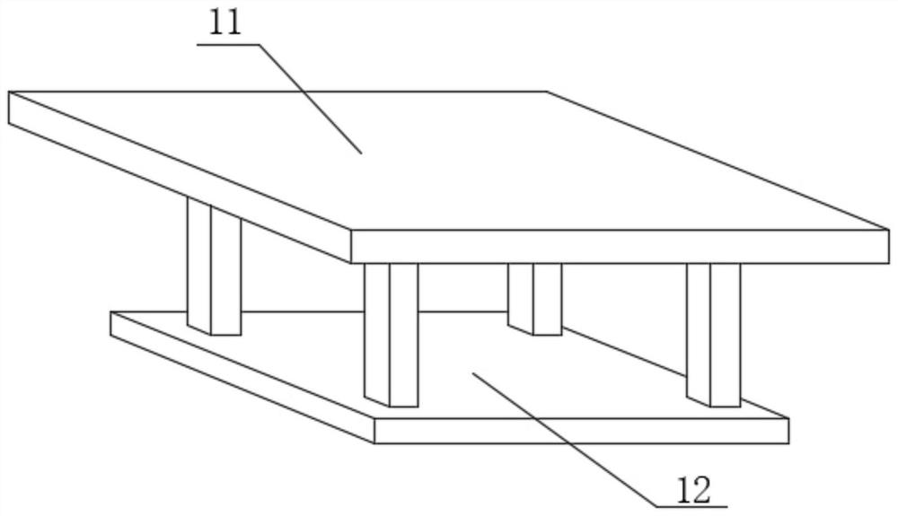
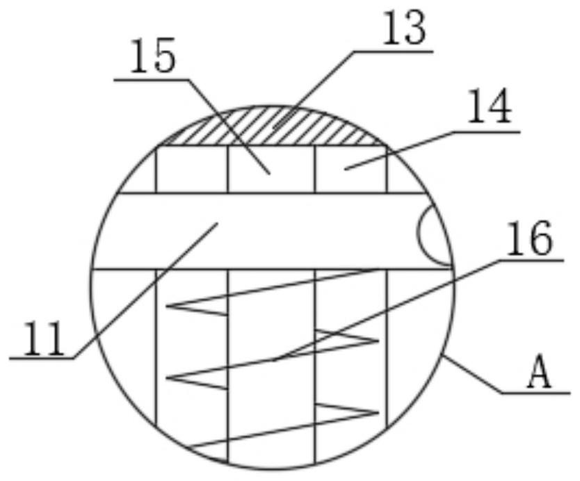
[0026] refer to Figure 1-5 , a high-voltage camera measurement device, including a base 1, an industrial camera pole 2 is fixedly installed on the top of the base 1, a plurality of industrial cameras 3 are fixedly installed on the industrial camera pole 2, and a kettle bottom support 4 is fixedly installed on the top of the base 1 , the top of the kettle bottom support 4 is fixedly installed with a high-pressure metering visible kettle 5, the top of the base 1 is slidably installed with a lighting device, the bottom of the base 1 is slidably installed with a support device, and the bottom end of the pillar 20 is fixedly installed on the support device. A button 21 is fixedly installed on the top of the pillar 20, a limit device is slidably installed on the pillar 20, a through hole 22 is provided on the base 1, and two telescopic rods 9 are installed symmetrically on the bottom of the base 1, and the bottom ends of the two telescopic rods 9 All are fixedly installed with guid...

Embodiment 2

[0035] refer to Figure 1-5 , a high-voltage camera measurement device, including a base 1, the top of the base 1 is fixedly installed with an industrial camera pole 2 by welding, and several industrial cameras 3 are fixedly installed on the industrial camera pole 2 by screws, and the top of the base 1 is fixedly installed by welding There is a kettle bottom support 4, and the top of the kettle bottom support 4 is fixed with a high-pressure metering visible kettle 5 by screws. The top of the base 1 is slidably installed with a lighting device, and the bottom of the base 1 is slidably installed with a support device. The bottom end of the pillar 20 is fixedly installed by welding, and the top of the pillar 20 is fixedly installed with a button 21 by welding. Telescopic rod 9, the bottom end of two telescopic rods 9 all is fixedly installed with guide wheel 10 by welding.

[0036] In this embodiment, the lighting device includes a light source bracket 6, an LED light source 7 a...


PUM


Abstract

The invention belongs to the technical field of metering devices, particularly relates to a high-voltage camera shooting metering device, and aims to solve the problem that the use efficiency of the device is reduced to a certain extent due to the fact that the device is inconvenient to move during use or the stability of the device cannot be ensured during use when the device can move. The following scheme is provided: the device comprises a base, an industrial camera supporting rod is fixedly installed at the top of the base, a plurality of industrial cameras are fixedly installed on the industrial camera supporting rod, a kettle bottom support is fixedly installed at the top of the base, a high-pressure metering visible kettle is fixedly installed at the top of the kettle bottom support, an illumination device is slidably installed at the top of the base, a supporting device is slidably installed at the bottom of the base, and the supporting device is fixedly provided with the bottom end of a supporting column. The device can be moved according to needs, use is convenient, time and labor are saved, the device can be supported after being moved, stability of the device during use is ensured, and the use efficiency of the device is further improved.

Description

technical field [0001] The invention relates to the technical field of metering devices, in particular to a high-voltage camera metering device. Background technique [0002] At present, the relevant instruments in the laboratory are developing in the direction of precision and automation. In the high-pressure seepage test, the low-permeability outlet measurement is still obtained by reading the electronic balance at the outlet through the back pressure control. In this way, a large error will often occur due to the excessive length of the pipeline, and even due to the excessive displacement of the liquid. Therefore, a high-voltage camera metering device is needed. The high-voltage camera metering device is manufactured with advanced technology, and all technical indicators have reached national standards. It has the advantages of high precision, good compressive strength, compact structure, beautiful appearance, energy saving and long service life. The frame and other acc...

Claims


Application Information

Patent Timeline
Patent Type & Authority Applications(China)
IPC IPC(8): G01N15/08H04N5/225
CPCG01N15/0806H04N23/50
Inventor 邰刘龙王刚涛吉刘斌
Owner JIANGSU TUOCHUANG SCI INSTR CO LTD
Why Eureka
Try Eureka