Rotary showing stand for new energy electronic products
What is AI technical title?
AI technical title is built by Patsnap AI team. It summarizes the technical point description of the patent document.
A technology for electronic products and display racks, which is applied in the field of display racks, and can solve the problems of display rack adjustment, poor adaptability, and display racks that cannot be rotated at will.
Inactive Publication Date: 2021-07-16
刘易坪
View PDF7 Cites 5 Cited by
Summary
Abstract
Description
Claims
Application Information
AI Technical Summary
This helps you quickly interpret patents by identifying the three key elements:
Problems solved by technology
Method used
Benefits of technology
Problems solved by technology
[0005] In order to overcome the shortcomings of general display racks that cannot be adjusted according to display needs, have poor adaptability, and the display rack as a whole cannot be rotated at will, the technical problem of the present invention is: to provide a booth that can be adjusted according to display needs and can rotate freely. Rotating display stand for new energy electronic products
Method used
Image
Click on the blue label to locate the original text in one second.
Reading with bidirectional positioning of images and text.
Examples
Embodiment 1
[0031] A rotating display stand for new energy electronic products, such as figure 1 , figure 2 , image 3 , Figure 4 As shown, it includes a base 1, a universal wheel 2, a lifting mechanism 3 and a display mechanism 4, four universal wheels 2 are evenly spaced at the bottom of the base 1, a lifting mechanism 3 is provided on the base 1, and a lifting mechanism 3 The upper part is provided with display mechanism 4.
[0032] When people need to use the rotating display stand, they can use this device. First, they can place the display in the display mechanism 4, then adjust it to a suitable height through the lifting mechanism 3, and finally manually push the display stand through the universal wheel 2 to rotate it. Push it to the exhibition hall for people to watch.
[0033] The lifting mechanism 3 includes a connecting piece 30, a support rod 31, a stage 32, a first wedge block 33 and a first spring 34. The top of the base 1 is rotatably provided with a support rod 31, ...
Embodiment 2
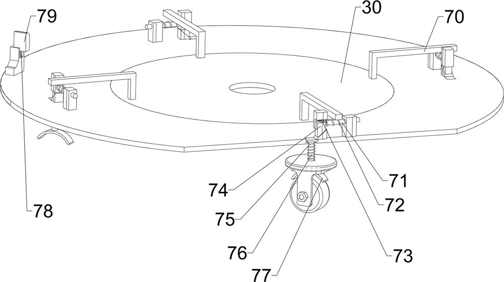
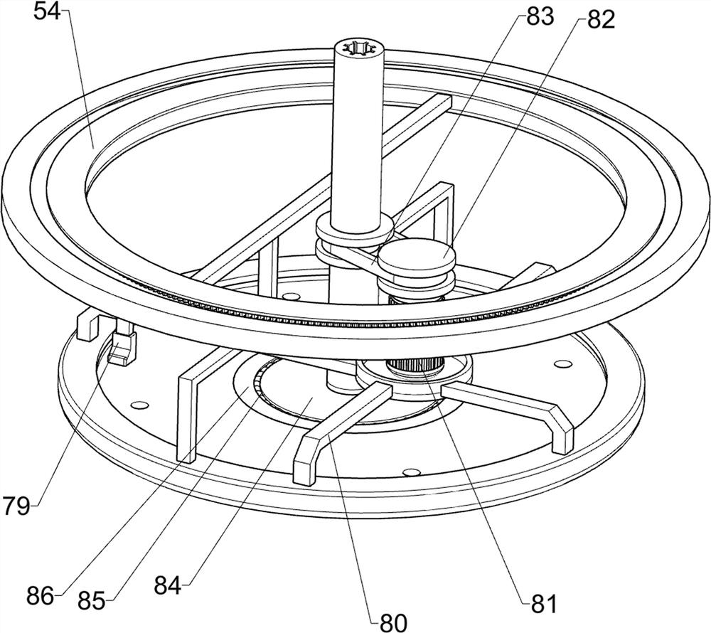
[0038] On the basis of Example 1, such as Figure 5 , Figure 6 , Figure 7 , Figure 8 , Figure 9 , Figure 10 As shown, a secondary display assembly 5 is also included. The secondary display assembly 5 includes a connecting frame 50, a ring gear 51, a loading box 52, a second gear 53 and a support frame 54, and the upper part of the support rod 31 is provided with a connecting frame 50. The outside of the connecting frame 50 is evenly spaced and rotated to be provided with six loading boxes 52, the lower side of the loading box 52 is provided with a second gear 53, the top of the base 1 is provided with a support frame 54, and the inside of the support frame 54 is provided with a ring gear 51. The ring gear 51 meshes with the second gear 53 .
[0039]When it is necessary to place some small objects for display, it can be placed in the loading box 52, and when it needs to be rotated for display, people can manually push the connecting frame 50, so that the ring gear 51 ...
PUM
Abstract
The invention relates to a showing stand, in particular to a rotary showing stand for new energy electronic products. The technical problem of the invention is to provide a new energy electronic product rotary display stand which can be adjusted according to display needs and can rotate an exhibition stand at will. According to the technical scheme, the rotary showing stand for the new energy electronic products comprises a base, universal wheels, a lifting mechanism and a showing mechanism; four universal wheels are evenly arranged at the bottom of the base at intervals, the lifting mechanism is arranged on the base, and the display mechanism is arranged on the upper portion of the lifting mechanism. The display stand can be adjusted according to display needs, and the display stand can be rotated at will; small parts or small objects are placed in a material carrying box, an object carrying table can rotate at will according to the small parts which people want to know, people can know the functions and some details of the object carrying table more visually, and the effect that the exhibition stand can be rotated at will is achieved.
Description
technical field [0001] The invention relates to a display stand, in particular to a rotating display stand for new energy electronic products. Background technique [0002] In today's society, electronic products are placed in electronic product display racks for display in the process of selling electronic products. This is well known to the public, and it is also an auxiliary device that facilitates customers to understand electronic products more conveniently when purchasing. . [0003] However, the height of general electronic product display racks is fixed, and the height cannot be adjusted according to the actual situation. It is difficult to understand its functions, and it is impossible to obtain a more detailed written introduction and detailed display. [0004] In view of the problems existing in the above-mentioned prior art, it is necessary to design a rotating display stand for new energy electronic products that can be adjusted according to the display requir...
Claims
Application Information
Patent Timeline
Application Date:The date an application was filed.
Publication Date:The date a patent or application was officially published.
First Publication Date:The earliest publication date of a patent with the same application number.
Issue Date:Publication date of the patent grant document.
PCT Entry Date:The Entry date of PCT National Phase.
Estimated Expiry Date:The statutory expiry date of a patent right according to the Patent Law, and it is the longest term of protection that the patent right can achieve without the termination of the patent right due to other reasons(Term extension factor has been taken into account ).
Invalid Date:Actual expiry date is based on effective date or publication date of legal transaction data of invalid patent.

