
A self-cleaning continuous fiber-reinforced composite 3D printing head

A reinforced composite material and continuous fiber technology, applied in the field of 3D printing, can solve problems such as nozzles being easily blocked, achieve the effects of easy cleaning, lower printing temperature, and high heating efficiency

Active Publication Date: 2022-04-22
SICHUAN UNIV
View PDF10 Cites 0 Cited by
  • Summary
  • Abstract
  • Description
  • Claims
  • Application Information

AI Technical Summary

Problems solved by technology

Compared with the prior art, the present invention effectively solves the technical problem that the existing nozzles are easily blocked

Method used


Image

  • A self-cleaning continuous fiber-reinforced composite 3D printing head
  • A self-cleaning continuous fiber-reinforced composite 3D printing head
  • A self-cleaning continuous fiber-reinforced composite 3D printing head

Examples


Embodiment 1

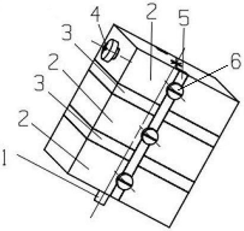
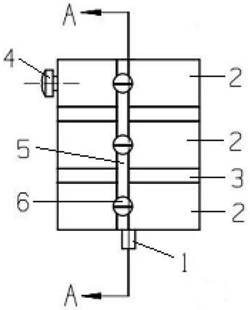
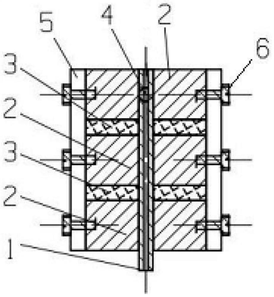
[0033] This embodiment provides a 3D printing head with no dead angle and self-cleaning function, which can prevent nozzles from being blocked during actual use, thereby facilitating continuous printing. Such as Figure 1-3 As shown, it includes a heating component, a fixed component and a metal capillary 1, and the specific structure, position and connection relationship of each component are as follows:

[0034] The heating assembly includes at least two stacked heating blocks 2. The heating block 2 can be an aluminum block or a stainless steel block. The heating block 2 is an existing conventional product, and its structural shape can be consistent with the existing conventional product. Each heating block 2 can satisfy the function of accurately controlling temperature. For example, the heating block 2 can be a square structure, and a temperature sensor and a heating rod can be arranged inside it to meet the functions of heating and temperature control.

[0035]Further, ...

Embodiment 2

[0041] On the basis of Example 1, in order to better heat the prepreg wire and ensure the plasticization quality of the prepreg wire, this embodiment adopts separate temperature control for each heating block 2. In actual operation, it is preferable to heat The heating temperature of block 2 decreases sequentially from top to bottom.

Embodiment 3

[0043] On the basis of Embodiment 1 or Embodiment 2, in order to better fix the heating component, this embodiment defines the structure of the fixing component, such as Figure 1-3 As shown, the fixing assembly includes a connecting plate 5 and a plurality of screws 6 , and the connecting plate 5 is fixed on the heating assembly through the screws 6 . Specifically, the two ends of the connecting plate 5 are respectively located on the sides of the uppermost and lowermost heating blocks 2, and each heating block 2 is provided with screw holes, and the connecting plate 5 is provided with corresponding screw holes, through which a plurality of screws 6 are respectively inserted. The connecting plate 5 can be fixed on the heating assembly through the screw holes. In order to ensure the overall stability of the heating assembly, preferably the fixing assembly is symmetrically fixed on both sides of the heating assembly.

[0044] The present invention will be specifically describe...


PUM


Abstract

The invention discloses a continuous fiber-reinforced composite material 3D printing head with self-cleaning function, which relates to the technical field of 3D printing, and includes a heating assembly, a fixing assembly and a metal capillary, and the heating assembly includes at least two stacked heating blocks , a heat insulation layer is set between adjacent heating blocks, and the heating assembly is fixed into a whole through a fixing assembly; the metal capillary runs through the heating assembly from top to bottom, and the two ends of the metal capillary are respectively the upper feeding end and the lower discharging end , the lower discharge end is used as a nozzle to extend out of the heating assembly. The invention integrates the feeding channel and the forming channel, and completely eliminates the dynamic dead angle in the printing head. At the same time, by designing the size of the feeding channel to match the diameter of the wire, the wire can peel off the resin that has stayed for a long time and bring out the residue that may be formed during the movement, realizing the self-cleaning function. Compared with the prior art, the invention effectively solves the technical problem that the existing nozzles are easily blocked.

Description

technical field [0001] The invention relates to the technical field of 3D printing, in particular to the technical field of 3D printing of continuous fiber reinforced composite materials, in particular to a 3D printing head of continuous fiber reinforced composite materials with self-cleaning function. Background technique [0002] There are two main modes of 3D printing of continuous fiber reinforced composites: one is online impregnation, resin filament and fiber dry yarn enter the print head from two places, and melt impregnation is realized in the print head. The second is off-line impregnation. The fibers are pre-melted and impregnated in the impregnation mold to prepare prepreg filaments for 3D printing, and then 3D printing is performed directly on the prepreg filaments. It is generally believed that the impregnation effect of fibers and resins in printing patterns using prepreg filaments is better, and the interface properties are better. [0003] At present, there ...

Claims


Application Information

Patent Timeline
Patent Type & Authority Patents(China)
IPC IPC(8): B29C64/112B29C64/295B29C64/35B29C64/321B33Y30/00B33Y40/00
CPCB29C64/112B29C64/295B29C64/35B29C64/321B33Y30/00B33Y40/00
Inventor 王孝军徐奔杨家操杨杰卫志美张刚龙盛如
Owner SICHUAN UNIV
Learn More