
Tire with tire bead structure
A bead and tire technology, applied in tire parts, tire sidewalls, transportation and packaging, etc., can solve the problems of increasing the overall weight of the tire, limited effect of puncture protection, and little contribution to support.
- Summary
- Abstract
- Description
- Claims
- Application Information
AI Technical Summary
Problems solved by technology
Method used
Image

Examples
Embodiment Construction
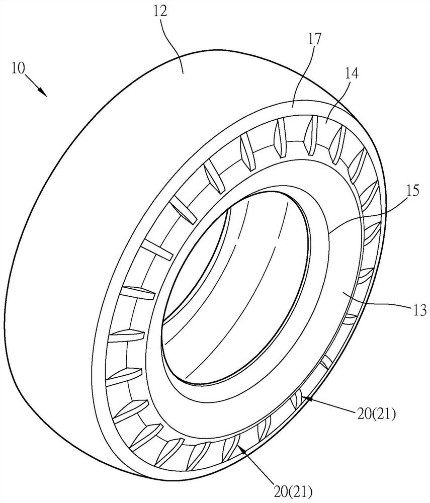
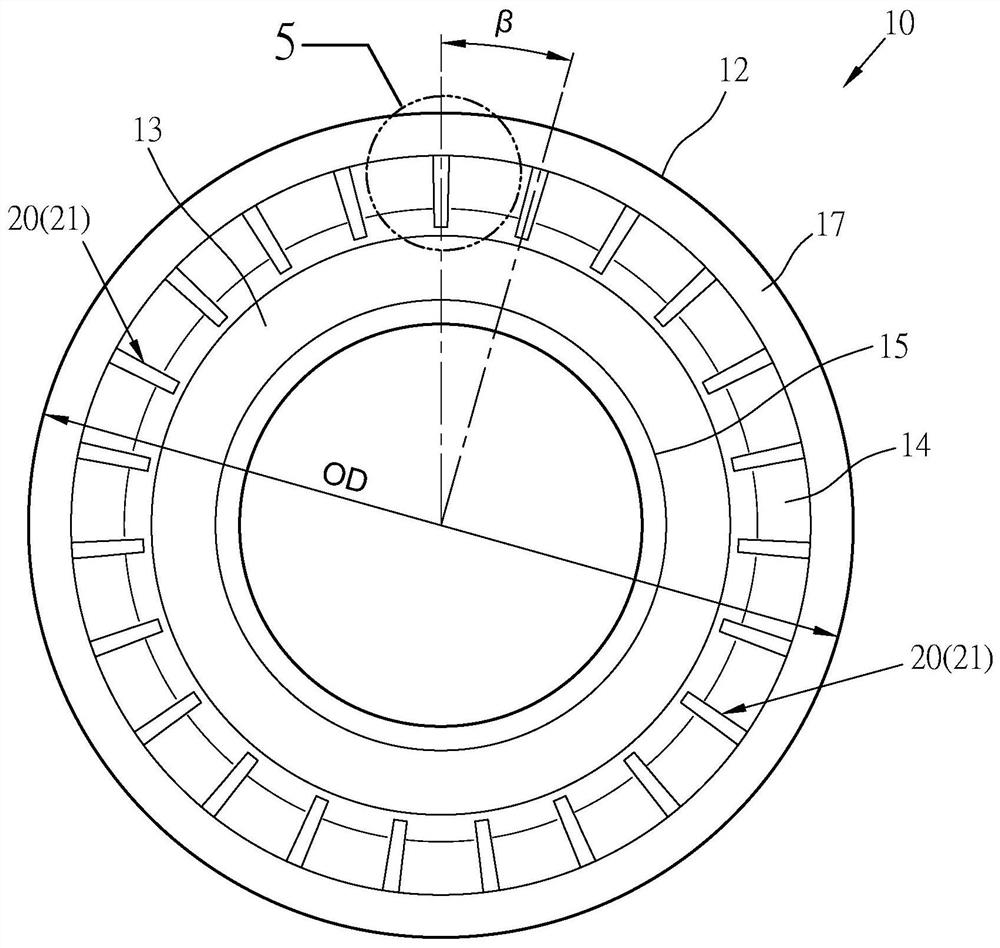
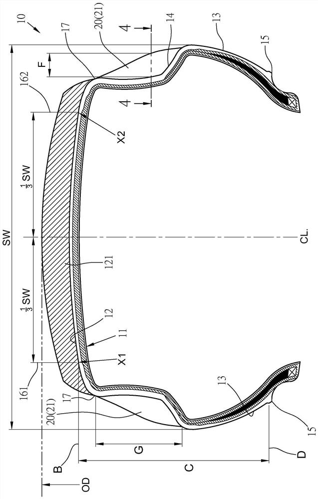
[0041] First please refer to Figure 1 to Figure 5 , A tire 10 with a bead structure provided by the present invention includes: a carcass 11 , a tread 12 , two bead 13 , and several protrusions 20 arranged on the two bead 13 .
[0042]The tire 10 has a tread 12 and two sidewalls 13 respectively extending from both sides of the tread 12, and a shoulder 17 is formed between each tread 12 and the sidewalls 13; each sidewall 13 is preset Each part has a groove part 14 which is recessed in a ring shape; the bead 13 has a ring-shaped rim line 15 respectively, and its outermost ring part is set as a first reference line D; the broken width of the tire 10 is Set as SW; the center line of the tire is set as CL, respectively set as a left reference line 161 and a right reference line 162 at the positions of 1 / 3 SW width on the left and right sides of the center line CL; the left reference line 161 When the right reference line 162 intersects with the bottom of the tread 12, there are ...
PUM
 Abstract
Description
Claims
Application Information