Placing rack for photovoltaic laminated part

A photovoltaic layer and rack technology, applied to internal accessories, rigid containers, containers, etc., can solve the problems of large output, high risk of hidden cracks, long time for front and rear line adjustment, etc., to facilitate turnover and reduce stacking area , The effect of reducing the risk of hidden cracks

Pending Publication Date: 2021-07-23
江苏彩虹永能新能源有限公司
View PDF0 Cites 0 Cited by
  • Summary
  • Abstract
  • Description
  • Claims
  • Application Information

AI Technical Summary

Problems solved by technology

[0002] At present, the intelligent line body of components is relatively extensive, the time process of front and rear line adjustment is too long, the output volume is too large, the laminated parts cann

Method used


Image

  • Placing rack for photovoltaic laminated part
  • Placing rack for photovoltaic laminated part

Examples


Embodiment Construction

[0019] The following are specific embodiments of the present invention and in conjunction with the accompanying drawings, the technical solutions of the present invention are further described, but the present invention is not limited to these embodiments.

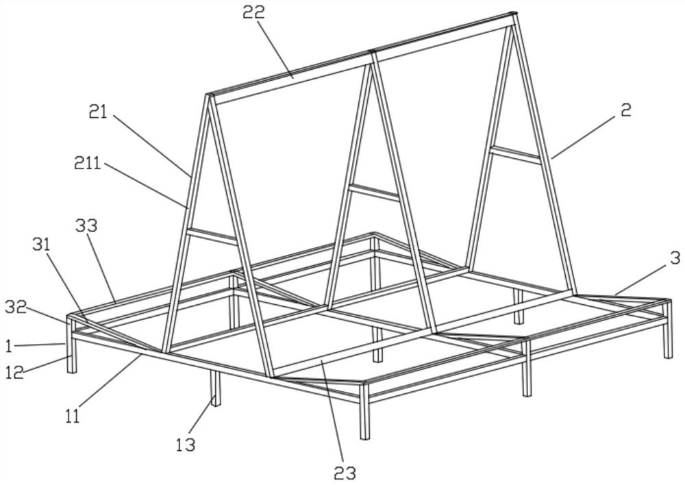
[0020] Such as Figures 1 to 2 As shown, a photovoltaic laminate placing frame includes a bottom frame 1, and a plurality of A-shaped brackets 21 are arranged side by side on the bottom frame 1. The rod 23 is fixed, and the two sides of the A-shaped support 21 respectively form side supports 2, and the bottom frame 1 is provided with a bottom support 3 at the lower end of the side supports 2, and the side of the bottom support 3 away from the side supports 2 is higher than the bottom frame 1. The plane, the side support 2 and the bottom support 3 are used to place the photovoltaic laminate, and the angle between them is greater than or equal to 90°.

[0021] An A-shaped bracket is arranged on the inner side of the bottom ...


PUM


Abstract

The invention discloses a placing rack for a photovoltaic laminated part. The placing rack comprises a bottom frame, wherein a plurality of A-shaped supports are arranged on the bottom frame side by side, the upper ends of the plurality of A-shaped supports are fixed through top rods, the lower ends of the plurality of A-shaped supports are fixed through bottom rods, side supports are formed on the two sides of the A-shaped supports, bottom supports are arranged at the positions, located at the lower ends of the side supports, of the bottom frame, the sides, away from the side supports, of the bottom supports are higher than the plane where the bottom frame is located, the side supports and the bottoms supports are used for placing the photovoltaic laminated part, and included angles between the side supports and the bottom supports are larger than or equal to 90 degrees. According to the placing rack, the side supports are gradually decreased in height from inside to outside, the bottom supports are gradually increased in height from inside to outside, and the side supports and the bottom supports act together to stably place the photovoltaic laminated part, so that the stacking area of the laminated part is reduced, the hidden crack risk of the laminated part in the carrying process is reduced, and circulation is convenient.

Description

technical field [0001] The invention relates to the technical field of component semi-finished product placement devices, in particular to a photovoltaic laminate placement rack. Background technique [0002] At present, the intelligent line body of components is relatively extensive, the time process of front and rear line adjustment is too long, the output volume is too large, the laminated parts cannot be circulated normally after lamination, and the risk of laying wooden pallets on the square of the laminated parts is too high, occupying a large area and stacking quantity Less, high risk of cracking. Contents of the invention [0003] The object of the present invention is to provide a photovoltaic laminate placement frame, the side support is in the form of gradually decreasing in height from the inside to the outside, and the bottom support is in the form of gradually increasing in height from the inside to the outside, the two work together to place the photovoltaic...

Claims


Application Information

Patent Timeline
IPC IPC(8): B65D6/08B65D25/02
CPCB65D11/14B65D25/02
Inventor 王立斌顾丽萍惠祺
Owner 江苏彩虹永能新能源有限公司
Why Eureka
Try Eureka