
Low-voltage lamp strip convenient to cut

A technology of light strips and low voltages, applied in the parts of lighting devices, semiconductor devices of light-emitting elements, lighting devices, etc., can solve the problems of inconvenience, reduced work efficiency, waste, etc., to reduce production costs and improve work efficiency. , the effect of convenient decorative use

Pending Publication Date: 2021-07-23
中山市争渡照明科技有限公司
View PDF0 Cites 0 Cited by
  • Summary
  • Abstract
  • Description
  • Claims
  • Application Information

AI Technical Summary

Problems solved by technology

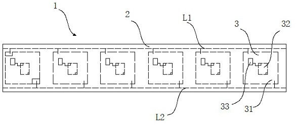
[0004] One is that the existing products are provided with resistors between multiple lamp beads. When the light strip needs to be cut and used, it needs to be cut according to the unit of multiple lamp beads and resistors.
In addition, due to the external installation of its resistance, the failure rate of the light strip increases
[0005] The second is that the circuits on the existing circuit boards are generally etched or punched out, and there are lines on both sides, and the production length is fixed. It is not easy to change the length of production, resulting in waste and increased decoration costs.
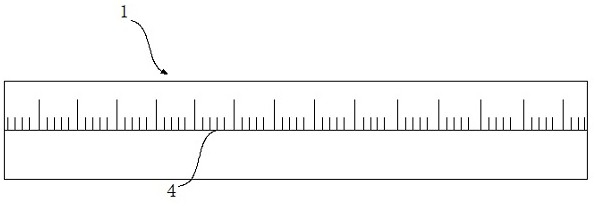
[0006] The third is that the traditional light strip does not have a scale layer, so that a ruler is needed for measurement when cutting, which is troublesome and inconvenient, increases labor intensity and reduces work efficiency

Method used


Image

  • Low-voltage lamp strip convenient to cut
  • Low-voltage lamp strip convenient to cut
  • Low-voltage lamp strip convenient to cut

Examples


Embodiment Construction

[0021] In order to make the purpose, technical solutions and advantages of the embodiments of the present invention clearer, the technical solutions in the embodiments of the present invention will be clearly and completely described below in conjunction with the drawings in the embodiments of the present invention. Obviously, the described embodiments It is a part of embodiments of the present invention, but not all embodiments. Based on the embodiments of the present invention, all other embodiments obtained by persons of ordinary skill in the art without creative efforts fall within the protection scope of the present invention.

[0022] In the description of the present invention, it should be noted that the terms "center", "upper", "lower", "left", "right", "vertical", "horizontal", "inner", "outer" etc. The indicated orientation or positional relationship is based on the orientation or positional relationship shown in the drawings, and is only for the convenience of desc...


PUM


Abstract

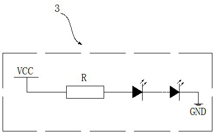
The invention relates to the technical field of lamp strips, in particular to a low-voltage lamp strip convenient to cut. The low-voltage lamp strip comprises a lamp strip body, the lamp strip body comprises a lamp panel, the lamp panel is provided with two metal wires, the two metal wires are longitudinally arranged in parallel, and a gap is reserved between the two metal wires; the two metal wires are respectively L1 and L2, and the positive and negative electrodes of the plurality of LED light source units are respectively welded on the metal wire L1 and the metal wire L2; and an independent LED light source unit is formed by a light-emitting diode and a current-limiting resistor or a current regulative diode, and the positive electrode and the negative electrode of the LED light source unit are welded to two wires of a lamp strip respectively to form an independent loop. The LED lamp strip can be cut at will to form a plurality of short lamp strips meeting the design requirement, and the plurality of short lamp strips can be combined to form a long lamp strip, so that the LED lamp strip is greatly convenient for people to use for decoration, the production cost is reduced, and the working efficiency is improved.

Description

technical field [0001] The invention relates to the technical field of light strips, in particular to a low-voltage light strip that is convenient to cut. Background technique [0002] With the development of society, people are decorating various activities, homes and other occasions, so they can send out various colors of light strips, which has become one of people's favorite decorations. The traditional light strip means that the LED light is welded on the copper wire or the strip-shaped flexible circuit board with a special process, and then connected to the power supply to emit light. It is named for its shape like a light strip when it emits light. [0003] The early process of the light strip is to weld the LED on the copper wire, and then put it on a PVC pipe or directly shape it with equipment. There are two types of round and flat. The root line is called the second line, the circle is added in front of the circle, that is, the second line of circle; the word fla...

Claims


Application Information

Patent Timeline
Patent Type & Authority Applications(China)
IPC IPC(8): F21S4/24F21V23/00F21V23/02F21Y115/10
CPCF21V23/002F21V23/005F21V23/02F21S4/24F21Y2115/10
Inventor 刘念白唐勇徐艳云田月
Owner 中山市争渡照明科技有限公司
Learn More