
Novel light-emitting diode (LED) lamp

A technology of LED lamps and LED chips, applied in the field of lighting, can solve the problems of large power supply, constant color, difficulty in making special-shaped lamps, etc., and achieve the effect of flexible and changeable appearance

Inactive Publication Date:
View PDF8 Cites 0 Cited by
  • Summary
  • Abstract
  • Description
  • Claims
  • Application Information

AI Technical Summary

Problems solved by technology

Its disadvantages are: the direct-ray LED light source is relatively close to the outer cover. To achieve the uniform light effect of the outgoing light, it is necessary to use a thicker or more filled uniform light cover, which sacrifices the brightness of the light. Generally, the dimming rate is often Around 30%
[0012] ④ It cannot be controlled, dimmed, or changed in color;
[0013] ⑤ The design of the reflection point of the laser process is complex, the life of the reflection point printed by ink is short, and the ink is easy to yellow and cause light decay;
[0014] ⑥ The brightness is restricted by the appearance structure, and the light source and brightness cannot be increased at will;
[0015] ⑦ The power supply is bulky and heavy, so only external power supply can be used;
[0017] The reason is that the LED chips of the current LED lamps are flat, which makes LED lamps usually flat, and it is difficult to make special-shaped lamps (the so-called special-shaped lamps are different from flat-plate LED lamps). Install a special-shaped lampshade on the flat LED chip, so that to achieve a uniform light effect for the outgoing light, it is necessary to use a thicker or more filled uniform light shield, thus sacrificing the brightness of the light. Generally, the dimming rate is often 30 %about

Method used


Image

  • Novel light-emitting diode (LED) lamp
  • Novel light-emitting diode (LED) lamp
  • Novel light-emitting diode (LED) lamp

Examples


Embodiment Construction

[0030] The present invention will be further described in detail below in conjunction with the accompanying drawings and specific embodiments, but the present invention is not limited to the following embodiments.

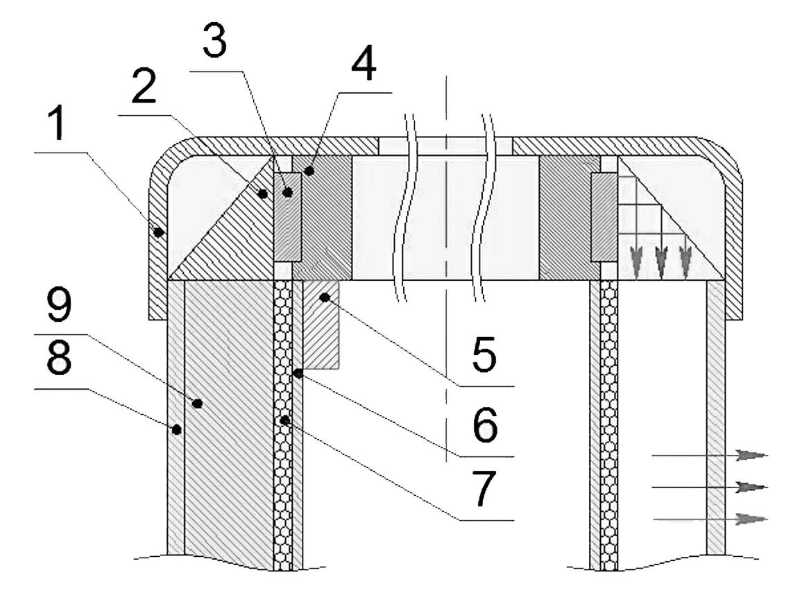
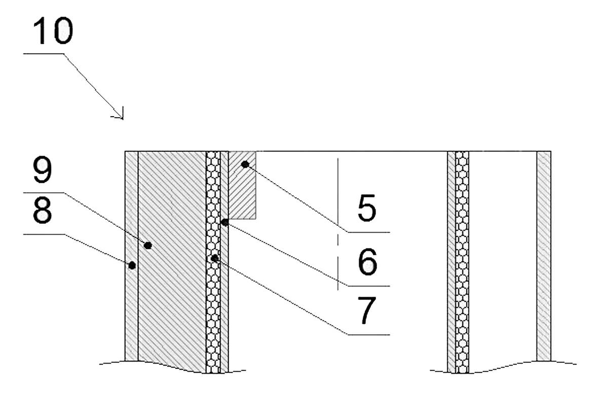
[0031] Such as figure 1 with 2 A new type of LED lamp is shown, which includes an LED chip 3 , a baseband 4 , a uniform light guide body 10 , and a prism 2 . The baseband 4 is an aluminum substrate or a soft copper-clad sheet, and the LED chips 3 are welded on the baseband 4 by reflow soldering. The LED chips 3 on the baseband 4 are closely connected and connected in series or in parallel. Arrows in the figure indicate the direction of light.

[0032] The uniform light guide body 10 is composed of a light guide body 9, a bead layer 7, and a reflective layer 6. The light guide body 9 is made of a transparent material with high light transmittance, and the bead layer 7 with high reflectivity is bonded to the light guide body 9. The inner side of the microbead laye...


PUM


Abstract

The invention discloses a novel light-emitting diode (LED) lamp, which comprises LED chips (3) and a base band (4) which is an aluminum base board or a soft band coated with a copper sheet. The LED chips (3) are welded on the base band (4) through reflow soldering, and the LED chips (3) on the base band (4) are tightly connected so as to achieve serial connection or parallel connection. The base band is the aluminum base board or the soft band coated with the copper sheets so that a light band formed by the LED chips and the base band can be bent or deformed to form an irregular LED chip band different from a flat type LED chip, accordingly various irregular LED lamps can be manufactured conveniently.

Description

technical field [0001] The invention belongs to the technical field of lighting, and in particular relates to an LED lamp. Background technique [0002] In recent years, decorative lighting has achieved expansive development. With the global incandescent lamp phase-out plan, my country's "low-carbon lighting" market environment, energy-saving and healthy lighting has become the mainstream of the lighting industry; with the improvement of household consumption levels, fashionable lighting and humanized design have become the lighting industry The characteristic culture of high-end consumption. [0003] Driven by favorable policies, the domestic LED lighting industry has an optimistic development environment and huge market potential. Based on the luminous efficiency of LEDs, it continuously breaks through the limitations of traditional light sources, providing a technical guarantee for LEDs to enter the lighting industry. [0004] Nowadays, the application of LED lighting p...

Claims


Application Information

Patent Timeline
Patent Type & Authority Applications(China)
IPC IPC(8): F21S8/00F21V13/00F21V21/108F21Y101/02
Inventor 李继红
Learn More