Hanging cabinet
A wall cabinet and cabinet body technology, applied in the field of wall cabinets, can solve the problems of single shape and single function, and achieve the effect of simple structure, good three-dimensional effect, and convenient installation and disassembly
- Summary
- Abstract
- Description
- Claims
- Application Information
AI Technical Summary
Problems solved by technology
Method used
Image
Examples
Embodiment 1
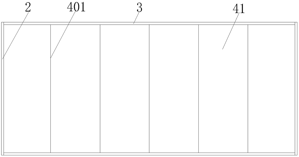
[0037] see Figure 1-2 The door panel 41 is a flat plate 3 with inclined surfaces 401 cut on both sides, and the inclined surfaces 401 on both sides of the door panel 41 are parallel to each other.
[0038] Between two adjacent door panels 41 is an inverted V-shaped structure that is concave toward the inside of the cabinet or a V-shaped structure that is convex toward the outside of the cabinet.
[0039] The two adjacent door panels 41 are connected by the inclined surfaces 401 that are attached to each other, and the angle θ between the outer surfaces of the two adjacent door panels 41 is in the range of 140°≤θ≤160°.
[0040] The door panel 41 in the door panel assembly 4 is set as a flat plate 3 with inclined surfaces 401 cut on the left and right sides, and the inclined surfaces 401 on both sides of the door panel 41 are parallel to each other, so that the adjacent two door panels 41 are pasted by the inclined surfaces 401 provided. At the same time, between two adjacent ...
Embodiment 2
[0046] see image 3 The door panel 41 is an elliptical arc-shaped panel protruding outward from the cabinet, and two fixedly connected door panels 41 form a pair.
[0047] The two door panels 41 in each pair are connected by the side planes that are attached to each other, and the two door panels 41 in each pair have a herringbone structure that is concave toward the interior of the cabinet.
[0048] The door panel 41 in the door panel assembly 4 is arranged as an elliptical arc-shaped panel protruding outward toward the cabinet, and two fixedly connected door panels 41 form a pair and are in a herringbone structure concave toward the cabinet.
[0049] During specific assembly, the side plate 2 and the door panel 41 are rotated and connected between the two pairs of door panels 41 in a herringbone structure, and each pair of door panels 41 is rotated around the side edge opposite to the axis of symmetry. Equally, when the hanging cabinet is in use, the hanging cabinet can be ...
Embodiment 3
[0052] see Figure 4 , the door panels 41 are semicircular arc-shaped panels that are concave toward the cabinet or convex toward the outside of the cabinet, and two of the door panels 41 that are fixedly connected form a pair.
[0053] The two door panels 41 in each pair are connected by the side planes that fit each other, and the two door panels 41 in each pair form an inverted M-shaped structure protruding outward toward the cabinet.
[0054] The door panel 41 in the door panel assembly 4 is set as a semicircular arc-shaped panel that protrudes outward from the cabinet or is concave inward from the cabinet, and two fixedly connected door panels 41 form a pair of inverted M-shaped structures that protrude outward toward the cabinet.
[0055] During specific assembly, the side panels 2 and the door panels 41 are rotated and connected by a rotating device, and are symmetrically arranged between two pairs of door panels 41 of an inverted M-shaped structure protruding outward f...
PUM
 Abstract
Description
Claims
Application Information
 - R&D
- Intellectual Property
- Life Sciences
- Materials
- Tech Scout
- Unparalleled Data Quality
- Higher Quality Content
- 60% Fewer Hallucinations
Browse by: Latest US Patents, China's latest patents, Technical Efficacy Thesaurus, Application Domain, Technology Topic, Popular Technical Reports.
© 2025 PatSnap. All rights reserved.Legal|Privacy policy|Modern Slavery Act Transparency Statement|Sitemap|About US| Contact US: help@patsnap.com


