Equipment in high-temperature ceramic sintering furnace

A technology of high-temperature ceramics and sintering furnace, which is applied in the field of high-temperature structural ceramics and can solve problems such as depressions and the influence of ceramic surfaces.

Inactive Publication Date: 2021-07-27
佛山市南海区德佰尼卫浴有限公司
View PDF3 Cites 2 Cited by
  • Summary
  • Abstract
  • Description
  • Claims
  • Application Information

AI Technical Summary

Problems solved by technology

[0003] In summary, the inventors found that the existing equipment in the sintering furnace mainly has the following defects: the sintering furnace adopts closed smelting in order to smelt the ceramics into a more exquisite one, and the raw materials will generate a large amount of heat while smelting. The gas will then fill the entire smelting chamber, so that as the gas continues to increase and the ceramics are in a soft state during the formation process, these gases will compress the forming ceramics in the gas-filled smelting chamber, and then As the gas continues to press the ceramic, the surface of the ceramic after molding will have a concave situation, so that the influence of the gas in the smelting chamber will directly have a great impact on the formation of the surface of the ceramic.

Method used


Image

  • Equipment in high-temperature ceramic sintering furnace
  • Equipment in high-temperature ceramic sintering furnace
  • Equipment in high-temperature ceramic sintering furnace

Examples


Embodiment 1

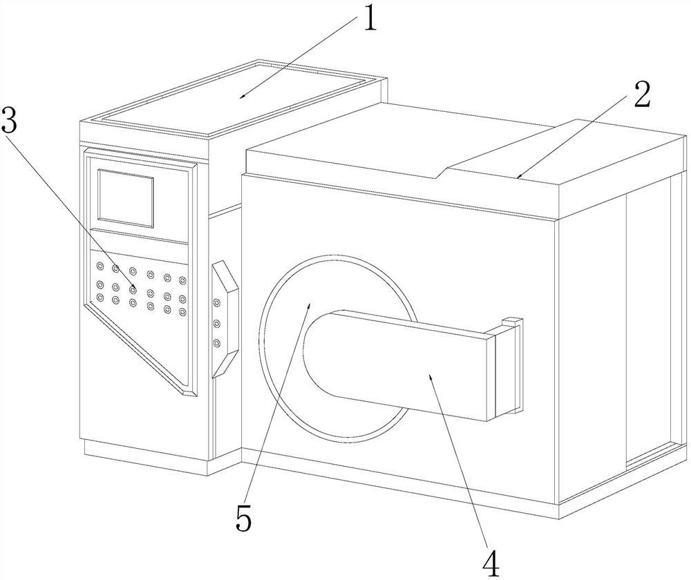
[0028] Figure 1 to Figure 6 Shown:

[0029] The invention provides a high-temperature ceramic sintering furnace equipment,

[0030] Its structure includes an electric control box 1, a furnace 2, a control terminal 3, a switch board 4, and a material inlet 5. The side of the electric control box 1 is electrically connected to the furnace 2, and the control terminal 3 is installed on the electric control On the end surface of the box 1 , the switch plate 4 is embedded in the front of the furnace 2 , and the material inlet 5 is movably connected with the switch plate 4 .

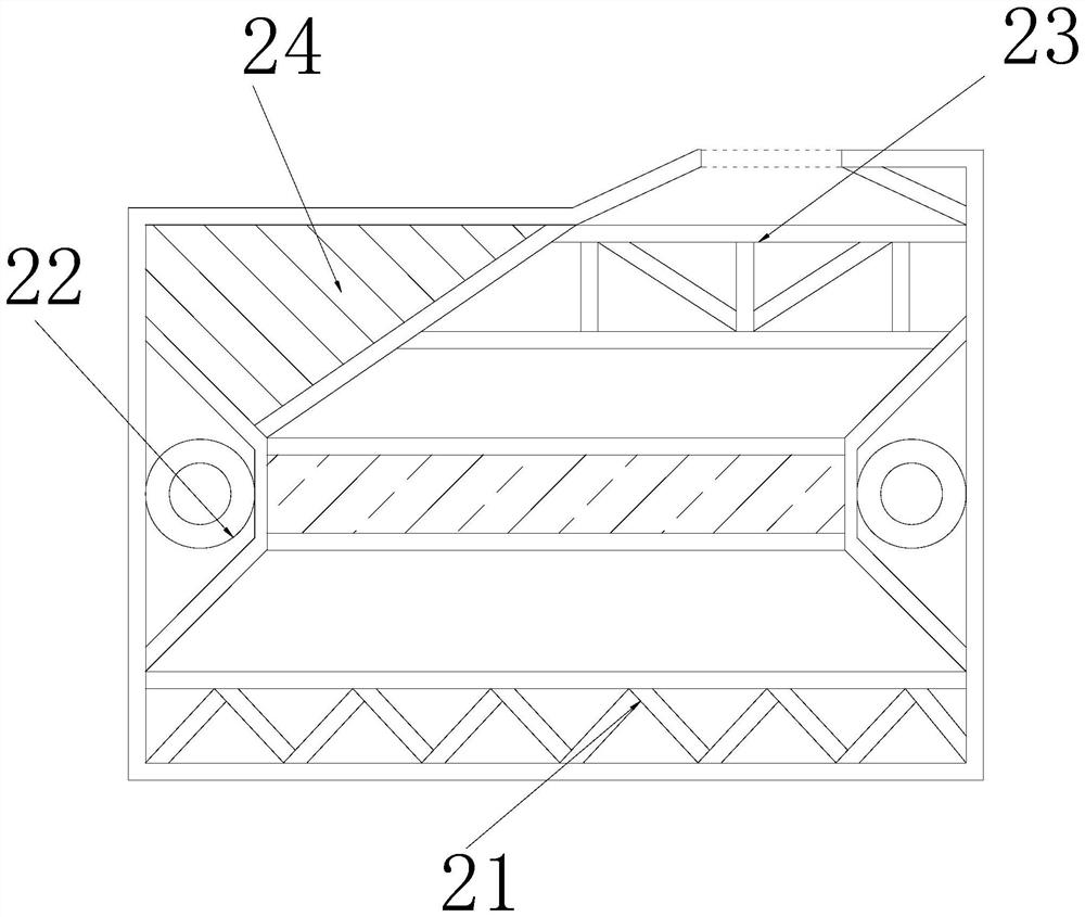
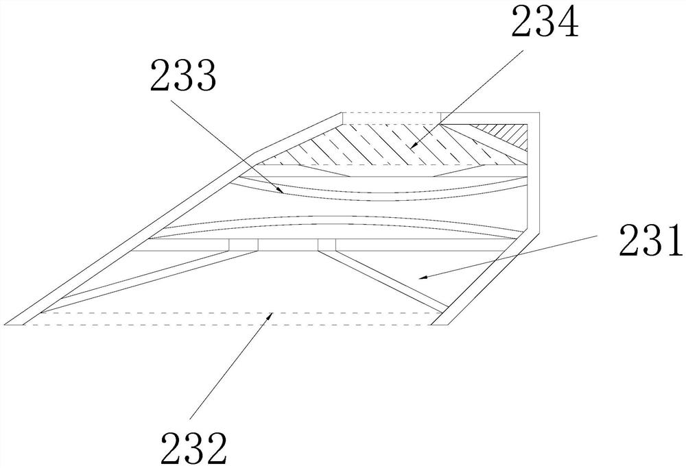
[0031] The sintering furnace 2 is provided with a forming table 21, a sintering device 22, a collecting device 23, and a fixed end 24. The sintering device 22 is installed above the forming table 21, and the collecting device 23 is installed above the side of the sintering device 22. The fixed end 24 is fixedly connected with the collecting device 23, the inside of the fixed end 24 is in a solid state, and i...

Embodiment 2

[0039] Figure 7 to Figure 9 Shown:

[0040] The invention provides a high-temperature ceramic sintering furnace equipment,

[0041] Its structure includes that the spray grid a4 is provided with a channel a41, a fixed box a42, and a filter layer a43, and the inner sides of the channel a41 are fixedly connected with the fixed box a42, and the filter layer b43 is embedded in the fixed box a42. The filter layer a43 is equipped with a multi-layer filter system, and the filter layer a43 can effectively isolate most impurities in the gas through its internal multi-layer filter, so that the finally discharged gas is clean gas.

[0042] Wherein, the fixed box a42 is provided with a bonding plate c1, a frame c2, a contact end c3, a fixing grid c4, and a spring c5, the side of the bonding plate c1 is integrated with the frame c2, and the contact end c3 is installed on the frame c2. At the upper end, the fixed grid c4 is embedded in the side of the contact end c3, the spring c5 is mov...


PUM


Abstract

The invention provides equipment in a high-temperature ceramic sintering furnace, which structurally comprises an electric control box, a sintering furnace body, a control terminal, a switch plate and a feed port; the side edge of the electric control box is electrically connected with the sintering furnace body, the control terminal is mounted on the end surface of the electric control box, and the switch plate is embedded in the front surface of the sintering furnace body. A large amount of hot gas is generated while high-temperature ceramic is put into the sintering furnace to be processed and formed, then an air bag installed at the upper end of a smelting cavity can continuously guide the hot gas to enter the air bag so that the hot gas can be expanded and discharged to the other end at the same time, and the hot gas can pass through a cooling layer while being discharged; the hot gas can be directly discharged to the outside after being physically cooled, so that the discharged gas cannot influence the outside temperature, and the situation that the hot gas in the smelting cavity is gradually increased and influences the end surface of the ceramic can be effectively prevented; and the leakproofness in the smelting cavity cannot be damaged through the one-way performance of the air bag.

Description

technical field [0001] The invention relates to the field of high-temperature structural ceramics, and more specifically relates to equipment in a high-temperature ceramic sintering furnace. Background technique [0002] The ceramic sintering furnace can effectively smelt the raw materials through high temperature through its own excellent properties such as wear resistance, high temperature resistance, and corrosion resistance, and the mold loaded inside the sintering furnace can effectively smelt the ceramics in the mold into corresponding shape, so that it can effectively play a good role in the shape formation of ceramics; [0003] In summary, the inventors found that the existing equipment in the sintering furnace mainly has the following defects: the sintering furnace adopts closed smelting in order to smelt the ceramics into a more exquisite one, and the raw materials will generate a large amount of heat while smelting. The gas will then fill the entire smelting cham...

Claims


Application Information

Patent Timeline
Patent Type & Authority Applications(China)
IPC IPC(8): F27D17/00
CPCF27D17/004F27D17/008
Inventor 张国锋
Owner 佛山市南海区德佰尼卫浴有限公司
Why Eureka
Try Eureka