Optical systems, lens modules and electronics
An optical system and lens technology, applied in optics, optical components, instruments, etc., can solve the problems of low image definition, large volume, and low resolution
- Summary
- Abstract
- Description
- Claims
- Application Information
AI Technical Summary
Problems solved by technology
Method used
Image

Examples
no. 1 example
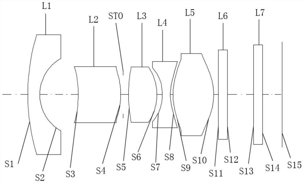
[0041] Please refer to Figure 1a and Figure 1b , the optical system of this embodiment includes sequentially from the object side to the image side along the optical axis direction:
[0042] The first lens L1 has a negative bending force, the object side S1 of the first lens L1 is convex, and the image side S2 is concave.
[0043] The second lens L2 has a positive bending force, the object side S3 of the second lens L2 is concave, and the image side S4 is convex.
[0044] The third lens L3 has a positive bending force, the object side S5 of the third lens L3 is convex, and the image side S6 is convex.
[0045] The fourth lens L4 has a negative bending force, the object side S7 of the fourth lens L4 is concave, and the image side S8 is concave.
[0046] The fifth lens L5 has a positive bending force, the object side S9 of the fifth lens L5 is a convex surface, and the image side S10 is a convex surface.
[0047] In addition, the optical system also includes a diaphragm STO...
no. 2 example
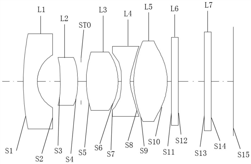
[0060] Please refer to Figure 2a and Figure 2b , the optical system of this embodiment includes sequentially from the object side to the image side along the optical axis direction:
[0061] The first lens L1 has a negative bending force, the object side S1 of the first lens L1 is convex, and the image side S2 is concave.
[0062] The second lens L2 has a positive bending force, the object side S3 of the second lens L2 is concave, and the image side S4 is convex.
[0063] The third lens L3 has a positive bending power, the object side S5 of the third lens L3 is a convex surface, and the image side S6 is a convex surface.
[0064] The fourth lens L4 has a negative bending force, the object side S7 of the fourth lens L4 is convex, and the image side S8 is concave.
[0065] The fifth lens L5 has a positive bending force, the object side S9 of the fifth lens L5 is a convex surface, and the image side S10 is a convex surface.
[0066] Other structures of the second embodiment...
no. 3 example
[0076] Please refer to Figure 3a and Figure 3b , the optical system of this embodiment includes sequentially from the object side to the image side along the optical axis direction:
[0077] The first lens L1 has a negative bending force, the object side S1 of the first lens L1 is convex, and the image side S2 is concave.
[0078] The second lens L2 has a positive bending force, the object side S3 of the second lens L2 is concave, and the image side S4 is convex.
[0079] The third lens L3 has a positive bending power, the object side S5 of the third lens L3 is a convex surface, and the image side S6 is a convex surface.
[0080] The fourth lens L4 has a negative bending force, the object side S7 of the fourth lens L4 is concave, and the image side S8 is concave.
[0081] The fifth lens L5 has a positive bending force, the object side S9 of the fifth lens L5 is a convex surface, and the image side S10 is a convex surface.
[0082] Other structures of the third embodiment...
PUM
 Abstract
Description
Claims
Application Information
 - R&D
- Intellectual Property
- Life Sciences
- Materials
- Tech Scout
- Unparalleled Data Quality
- Higher Quality Content
- 60% Fewer Hallucinations
Browse by: Latest US Patents, China's latest patents, Technical Efficacy Thesaurus, Application Domain, Technology Topic, Popular Technical Reports.
© 2025 PatSnap. All rights reserved.Legal|Privacy policy|Modern Slavery Act Transparency Statement|Sitemap|About US| Contact US: help@patsnap.com