Enhanced elevator flat traveling cable based on remote monitoring
A technology for remote monitoring and accompanying cables, which is applied in the direction of flat/ribbon cables, insulated cables, and cables. convenient effect
- Summary
- Abstract
- Description
- Claims
- Application Information
AI Technical Summary
Problems solved by technology
Method used
Image

Examples
Embodiment 1
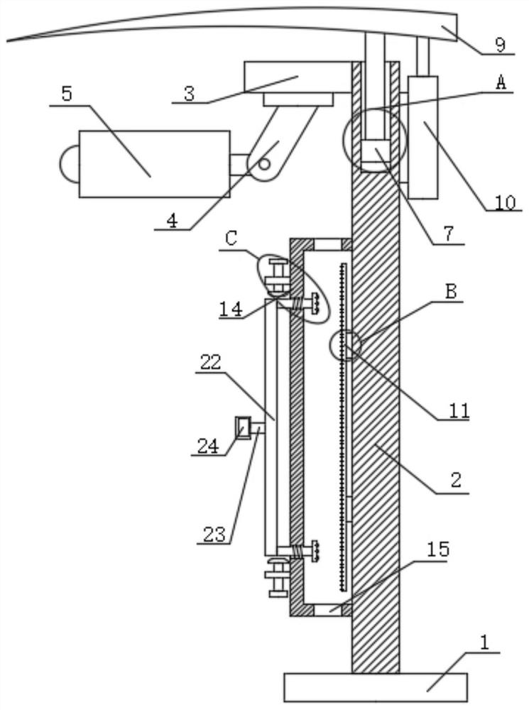
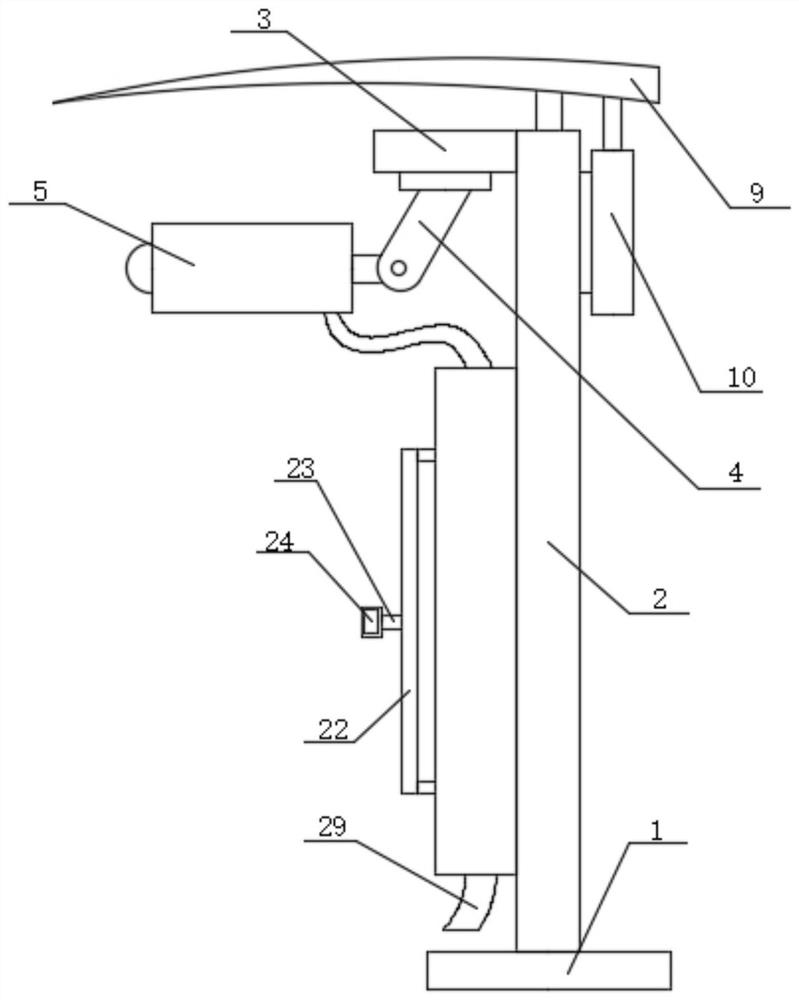
[0026] refer to Figure 1-5 , an enhanced elevator flat accompanying cable based on remote monitoring, including a bottom plate 1 and a cable 29, a support plate 2 is fixedly installed on the top of the bottom plate 1, a side plate 3 is fixedly installed on one side of the support plate 2, and the bottom of the side plate 3 is fixed Movable plate 4 is installed, and camera 5 is movably installed on movable plate 4, and the top of support plate 2 is slidably installed with blocking device, and the other side of support plate 2 is fixedly installed with electric push rod 10, and the output shaft of electric push rod 10 is connected with The shielding device is fixedly connected, and one side of the support plate 2 is fixedly equipped with a material guide plate 11, and several installation rods 12 are installed on the material guide plate 11, and several installation rods 12 are fixedly equipped with a material guide cylinder 13, and the support plate One side of 2 is fixedly in...
Embodiment 2
[0035] refer to Figure 1-5 , an enhanced elevator flat accompanying cable based on remote monitoring, including a bottom plate 1 and a cable 29, the top of the bottom plate 1 is installed with a support plate 2 by welding, and one side of the support plate 2 is installed with a side plate 3 by welding, and the side plate 3 The movable plate 4 is installed at the bottom by welding, the camera 5 is installed movable on the movable plate 4, the top of the support plate 2 is slidingly installed with a blocking device, the other side of the support plate 2 is installed with an electric push rod 10 through screws, and the electric push rod 10 The output shaft is fixedly connected with the shielding device, one side of the support plate 2 is installed with a material guide plate 11 by welding, and several installation rods 12 are installed on the material guide plate 11, and several installation rods 12 are installed with guide plates by welding. Barrel 13, one side of support plate...
PUM
 Abstract
Description
Claims
Application Information
 - Generate Ideas
- Intellectual Property
- Life Sciences
- Materials
- Tech Scout
- Unparalleled Data Quality
- Higher Quality Content
- 60% Fewer Hallucinations
Browse by: Latest US Patents, China's latest patents, Technical Efficacy Thesaurus, Application Domain, Technology Topic, Popular Technical Reports.
© 2025 PatSnap. All rights reserved.Legal|Privacy policy|Modern Slavery Act Transparency Statement|Sitemap|About US| Contact US: help@patsnap.com