Lifting device for sunken anchor of sailing ship

A lifting device and a technology for sailing ships, which are applied in the field of sailing ships, can solve the problems of inconvenient anchor lifting operations, etc., and achieve the effect of easy adjustment, easy installation and fixation

Inactive Publication Date: 2020-09-04
JIANGSU MARITIME INST
0 Cites 2 Cited by

AI-Extracted Technical Summary

Problems solved by technology

[0004] The purpose of the present invention is to solve the problem in the prior art that most of the anchors in the prior art are salvaged with artificial tying ropes ...

Method used

In the present invention, drive motor 2 can drive telescopic sleeve bar to rotate, thereby drives sleeve 3 to rotate, and then retracts steel cable 4, drives first support plate 5 and moving mechanism to move in vertical direction, drives two The clamping plate 6 moves in the vertical direction. Since the first external thread and the second external thread have opposite helical directions, turning the threaded rod 16 can drive the movement of the two nuts 17, driving the clamping plate 6 to move in the horizontal direction, so that the two The clamping plate 6 cooperates to facilitate fixing the sinking anchor. The telescopic cylinder 25 can drive the third slide plate 24 and the second cover plate 23 ...

Abstract

The invention discloses a lifting device for a sunken anchor of a sailing ship. The device comprises two mounting plates which are symmetrically arranged, wherein the two mounting plates are both vertically arranged; a driving motor is arranged on the side wall of the mounting plate; the output end of the driving motor penetrates through the side wall of the mounting plate and is connected with atelescopic sleeve rod; the telescopic sleeve rod is rotationally connected with the mounting plate; a sleeve is arranged outside the telescopic sleeve rod in a sleeving manner; a steel cable is arranged outside the sleeve; the lower end of the steel cable is fixedly connected with a horizontally-arranged first supporting plate; the first supporting plate is of a hollow structure; a moving mechanism is arranged in the first supporting plate; two symmetrically-arranged clamping plates are arranged at the lower end of the moving mechanism; the two mounting plates are of a hollow structure; movingbodies are arranged in the two mounting plates; and mounting mechanisms are arranged at the lower ends of the two moving bodies. Manual rope tying for salvaging is not needed, and lifting operation can be conveniently conducted on the sunken ship anchor.

Application Domain

Anchor handling/lashing

Technology Topic

Electric machineryDrive motor +3

Image

  • Lifting device for sunken anchor of sailing ship
  • Lifting device for sunken anchor of sailing ship
  • Lifting device for sunken anchor of sailing ship

Examples

  • Experimental program(1)

Example Embodiment

[0024] The technical solutions in the embodiments of the present invention will be clearly and completely described below with reference to the accompanying drawings in the embodiments of the present invention. Obviously, the described embodiments are only a part of the embodiments of the present invention, but not all of the embodiments.
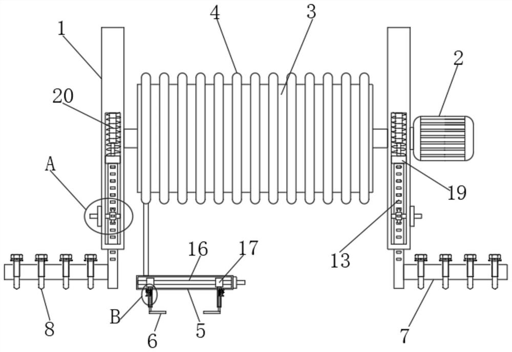
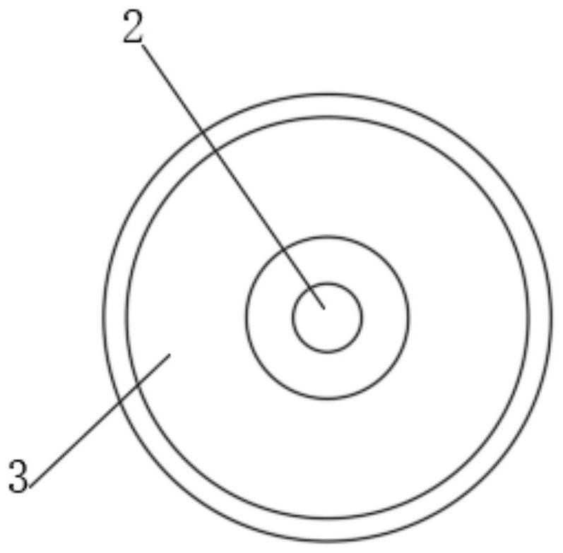
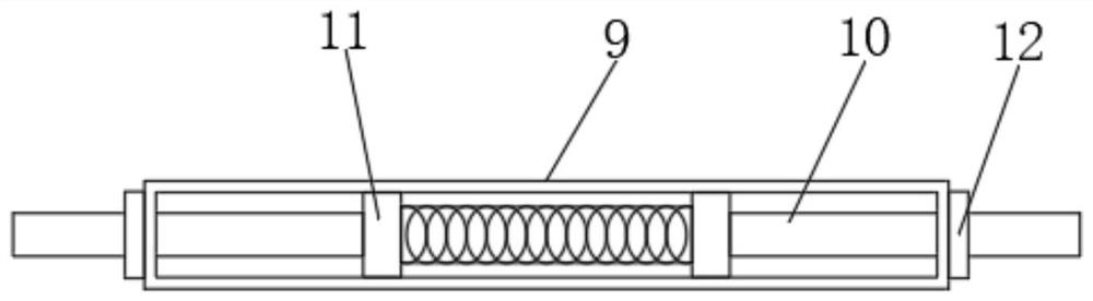
[0025] refer to Figure 1-5 , a lifting device for ship sinking anchor, comprising two symmetrically arranged mounting plates 1, both of which are vertically arranged, and a drive motor 2 is arranged on the side wall of the mounting plate 1, and the drive motor 2 The output end penetrates the side wall of the mounting plate 1 and is connected with a telescopic sleeve rod. The telescopic sleeve rod is rotatably connected with the mounting plate 1. The outer sleeve of the telescopic sleeve rod is sleeved with a sleeve 3, and the outside of the sleeve 3 is provided with a steel cable 4 , the lower end of the wire rope 4 is fixedly connected with a horizontally arranged first support plate 5, and the first support plate 5 is a hollow structure, the first support plate 5 is provided with a moving mechanism, and the lower end of the moving mechanism is provided with two symmetrically arranged The clamping plate 6, the two mounting plates 1 are both hollow structures, and the two mounting plates 1 are provided with moving bodies, and the lower ends of the two moving bodies are provided with mounting mechanisms, and the mounting mechanisms include a horizontally arranged second support Plate 7, a plurality of mounting screws 8 are inserted on the second support plate 7, and the plurality of mounting screws 8 are evenly distributed on the second support plate 7, and the telescopic sleeve rod includes a horizontally arranged first support rod 9, the first support The rod 9 is a hollow structure, and the first support rod 9 is inserted with two symmetrically arranged second support rods 10. The two second support rods 10 are fixedly connected with a vertically arranged first slide plate 11, and the two second support rods 10 are fixedly connected. Each of the first sliding plates 11 is slidably connected to the inside of the first support rod 9 , the two first sliding plates 11 are connected by a plurality of first springs, and both ends of the first support rod 9 are provided with the second support rod 10 The matching first sliding lock block 12, the drive motor 2 can drive the telescopic sleeve rod to rotate, thereby driving the sleeve 3 to rotate, and then retracting the wire 4, driving the first support plate 5 and the moving mechanism to move in the vertical direction, The two clamping plates 6 are driven to move in the vertical direction. Since the first external thread and the second external thread are arranged in opposite directions, rotating the threaded rod 16 can drive the two nuts 17 to move and drive the clamping plate 6 to move in the horizontal direction. The two clamping plates 6 are matched to facilitate fixing the sinking anchor, and the telescopic cylinder 25 can drive the third sliding plate 24 and the second sleeve plate 23 to move in the vertical direction, which is convenient for secondary adjustment of the working position of the clamping plate 6;
[0026]The moving main body includes a vertically arranged third support plate 13 , and the third support plate 13 is arranged through the side wall of the mounting plate 1 , and a horizontally arranged rotating rod 14 is rotatably connected in the mounting plate 1 , and the rotating rod 14 penetrates the mounting plate 1 . The side wall of the third support plate 13 is provided with a gear 15, the side wall of the third support plate 13 is provided with a tooth slot engaged with the gear 15, the moving mechanism includes a horizontally arranged threaded rod 16, and the threaded rod 16 is connected with the gear 15. The inner wall of the first support plate 5 is rotatably connected, and the threaded rod 16 is arranged through the side wall of the first support plate 5. Two symmetrically arranged nuts 17 are sleeved on the threaded rod 16, and telescopic sleeve plates are connected to the two nuts 17. , the side wall of the first support plate 5 is provided with a first strip-shaped opening matched with the telescopic sleeve plate, and the two telescopic sleeve plates are arranged through the first strip-shaped opening, and the side wall of the mounting plate 1 is slidably connected with The second sliding lock block 18, and the second sliding lock block 18 is matched with the rotating rod 14, the upper end of the third support plate 13 is fixedly connected with a horizontally arranged second sliding plate 19, and the two ends of the second sliding plate 19 are installed with The inner wall of the plate 1 is slidably connected, and the upper end of the second sliding plate 19 is connected to the inner wall of the mounting plate 1 through a plurality of telescopic connecting rods 20. The telescopic connecting rods 20 include a vertically arranged first connecting rod, and the first connecting rod is a hollow structure. And the first connecting rod is inserted with a vertically arranged second connection, the outside of the telescopic connecting rod 20 is sleeved with a second spring, and the external thread of the threaded rod 16 is composed of a symmetrically arranged first external thread and a second external thread. , the first external thread and the second external thread are arranged in opposite directions, and the two nuts 17 are respectively sleeved on the first external thread and the second external thread, the threaded rod 16 is sleeved with a nut 21, and the nut 21 Located outside the first support plate 5 , the telescopic sleeve plate includes a vertically arranged first sleeve plate 22 , the first sleeve plate 22 is a hollow structure, and a vertically arranged second sleeve plate is inserted into the first sleeve plate 22 23. The lower end of the second set of plates 23 is fixedly connected with the card board 6, and the upper end of the second set of plates 23 is fixedly connected with a third sliding plate 24 arranged horizontally, and the third sliding plate 24 is connected to the first set of plates through a plurality of third springs. 22 is connected to the inner wall, the side wall of the first cover plate 22 is provided with a second strip-shaped opening matched with the third slide plate 24, and the third slide plate 24 is arranged through the second strip-shaped opening. There is a telescopic cylinder 25 on the wall, and the output end of the telescopic cylinder 25 is connected with the side wall of the third sliding plate 24, the second support rod 10 can move in the first support rod 9, so as to adjust the working range of the telescopic sleeve rod , the first sliding lock block 12 can lock the second support rod 10 to ensure the stability of the working state of the telescopic sleeve rod, and the rotating rod 14 can drive the gear 15 to rotate, thereby driving the third support plate 13 to move in the vertical direction, It is convenient to adjust the working position of the installation mechanism, and the second support plate 7 cooperates with the installation screw 8 to facilitate the installation and fixation of the pulling device.
[0027] In the present invention, the drive motor 2 can drive the telescopic sleeve rod to rotate, thereby driving the sleeve 3 to rotate, and then retracting the wire 4, driving the first support plate 5 and the moving mechanism to move in the vertical direction, and driving the two clamping plates 6 When moving in the vertical direction, since the first external thread and the second external thread are arranged in opposite directions, rotating the threaded rod 16 can drive the two nuts 17 to move, drive the clamping plate 6 to move in the horizontal direction, and make the two clamping plates 6 move in the horizontal direction. In cooperation, it is convenient to fix the sinking anchor. The telescopic cylinder 25 can drive the third sliding plate 24 and the second sleeve plate 23 to move in the vertical direction, which is convenient for the secondary adjustment of the working position of the clamping plate 6. The second support rod 10 can It moves in the first support rod 9 to adjust the working range of the telescopic sleeve rod. The first sliding lock block 12 can lock the second support rod 10 to ensure the stability of the working state of the telescopic sleeve rod. The gear 15 is driven to rotate, thereby driving the third support plate 13 to move in the vertical direction, which is convenient for adjusting the working position of the installation mechanism.
[0028] The above description is only a preferred embodiment of the present invention, but the protection scope of the present invention is not limited to this. The equivalent replacement or change of the inventive concept thereof shall be included within the protection scope of the present invention.

PUM

no PUM

Description & Claims & Application Information

We can also present the details of the Description, Claims and Application information to help users get a comprehensive understanding of the technical details of the patent, such as background art, summary of invention, brief description of drawings, description of embodiments, and other original content. On the other hand, users can also determine the specific scope of protection of the technology through the list of claims; as well as understand the changes in the life cycle of the technology with the presentation of the patent timeline. Login to view more.

Similar technology patents

Water mixing valve of water heater

Owner:SHANDONG ANALYSIS & TEST CENT

Light distribution measuring device and method for crop canopy

ActiveCN102680084AEasy to adjustFlexible measurement position
Owner:BEIJING RES CENT FOR INFORMATION TECH & AGRI

Leveling ruler flat underboarding mortar bedding method

ActiveCN103572774AEasy to adjustImprove device installation speed
Owner:CHINA MCC20 GRP CORP

Multi-angle adjusting frame for millimeter-wave radar

Owner:HEFEI HUMP ELECTRONICS TECH DEV CO LTD

Classification and recommendation of technical efficacy words

  • Easy to adjust
  • Easy to install and fix

High-isolation double-unit MIMO (multiple input multiple output) antenna array

InactiveCN102832452AEasy to adjustgood impedance characteristics
Owner:GUILIN UNIV OF ELECTRONIC TECH

Method for regulating high power laser apparatus light path alignment

InactiveCN101266340Asimple equipmentEasy to adjust
Owner:SHANGHAI INST OF OPTICS & FINE MECHANICS CHINESE ACAD OF SCI

Conductive rubber and application thereof

ActiveCN102176341AGood for dust resistanceEasy to adjust
Owner:DONGGUAN MEMTECH ELECTRONICS MEMTECH ELECTRONICS PRO +2

Preparation method and application of carbon quantum dot/metal organic skeleton catalyst

ActiveCN107754861AImprove photocatalytic reactivityEasy to adjust
Owner:FUJIAN INST OF RES ON THE STRUCTURE OF MATTER CHINESE ACAD OF SCI

Clamping structure of circuit board

InactiveCN108012498AEasy take-out and feed-inEasy to install and fix
Owner:曹诗晴

Portable spherical infrared camera

InactiveCN104284072ASimplify camera structureEasy to install and fix
Owner:ZHONGSHAN ANLING STAR ELECTRONICS TECH

Automobile front suspension lower swing arm assembly

Owner:Ningbo Runzhou Automobile Fittings Co Ltd
Why Eureka
Try Eureka