Bonding positioning device convenient to disassemble

A positioning device and bonding technology, applied in brackets and other directions, can solve problems such as spending a lot of time and energy, violations, and poor orthodontic experience, and achieve the effects of increased disassembly difficulty, accurate and fast operation, and long disassembly time.

Pending Publication Date: 2021-07-30
GUANGZHOU OO MEDICAL SCI LTD
View PDF0 Cites 0 Cited by
  • Summary
  • Abstract
  • Description
  • Claims
  • Application Information

AI Technical Summary

Problems solved by technology

At present, most of the transfer devices on the market are hard to remove the transfer device from the tooth surface with orthodontic tools after the brackets are bonded to the tooth surface, and the orthodontist needs to manually operate the transfer device from the tooth surface. However, due to the narrow environment of the oral cavity, the orthodontist does not have much room to operate to remove the transfer device. It usually takes a lot of time and energy, which increases the work intensity and operation time of the orthodontist, which violates the principle of indirect adhesion. The original intention of directly reducing the work intensity of orthodontists
Moreover, the orthodontic experience of orthodontic patients is poor, so orthodontists often give up indirect bonding technology and use direct bonding technology to bond brackets for orthodontic patients

Method used


Image

  • Bonding positioning device convenient to disassemble
  • Bonding positioning device convenient to disassemble
  • Bonding positioning device convenient to disassemble

Examples


Embodiment 1

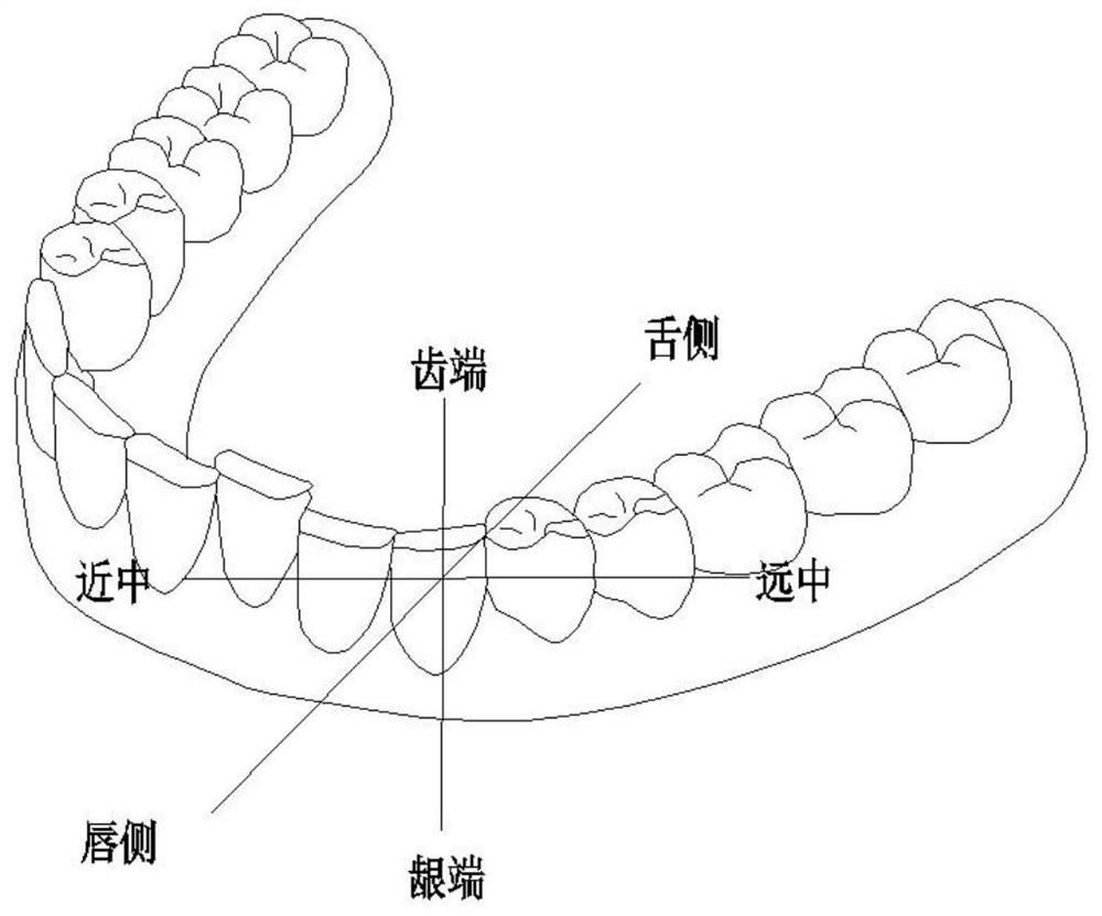
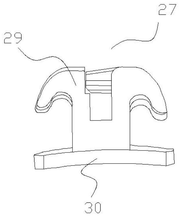
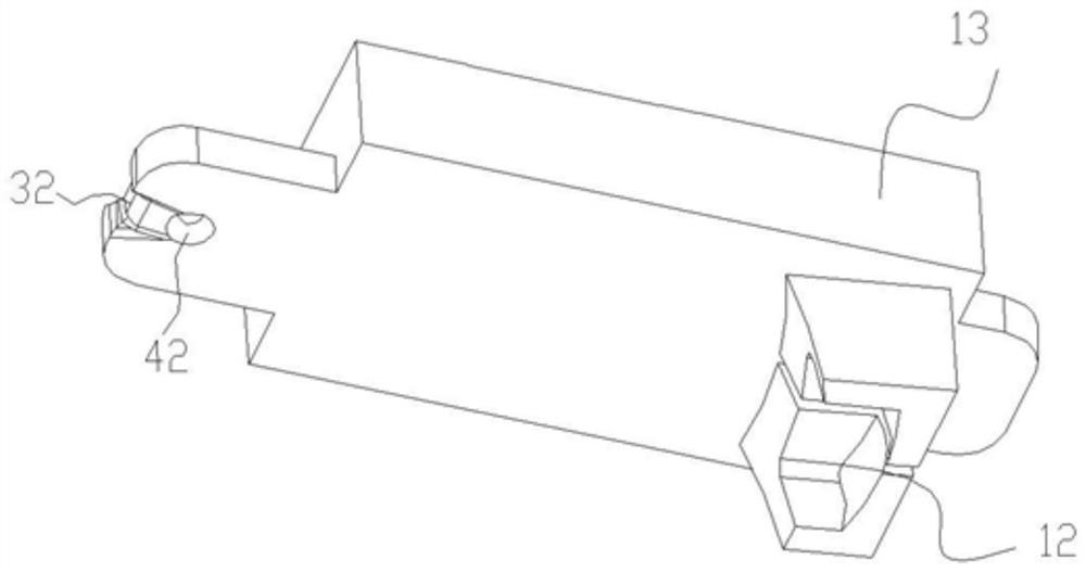
[0063] see Figure 1-12 and Figure 20 , an adhesive positioning device 10, comprising at least one positioning unit 11, the positioning unit 12 includes a tooth positioning structure 13 and a bracket positioning structure 12 connected to each other, the tooth positioning structure 12 is used to abut against the tooth end surface of the tooth, and the bracket positioning The structure 12 is used to clamp the bracket 27 and release the bracket 27 on the tooth surface.

[0064] The tooth positioning structure 13 includes a take-off piece, and the take-off piece is used for hooking, clamping or abutting by the take-off tool. The extractor is located on at least one of the labial side, lingual side, tooth end surface and gingival end surface of the tooth positioning structure or simultaneously on two or more than two sides.

[0065] The take-off part has an extension suitable for the take-off tool (for example, probe, tweezers), and the take-off tool exerts a force on the take-o...

Embodiment 2

[0099] see Figure 13 , this embodiment provides an adhesive positioning device for orthodontics, its structure is basically the same as that of the adhesive positioning device in Embodiment 1, the difference is that the third clamping piece 22 is along its tooth end The width of the fourth clamping piece 23 gradually increases toward the gingival end, and the width of the fourth clamping piece 23 gradually increases along the tooth end toward the gingival end. The change of the width of the third clamping piece 22 and the change of the width of the fourth clamping piece 23 facilitate the convergence of the elastic clamping force of the third clamping piece 22 and the fourth clamping piece 23, so that the first elastic clamping The block 14 and the second elastic clamping block 15 can securely clamp the bracket 27 .

[0100] The rest of the structure of this embodiment is the same as that of Embodiment 1, and will not be described in detail here.

Embodiment 3

[0102] see Figure 14 , this embodiment provides an adhesive positioning device for orthodontics, its structure is basically the same as that of the adhesive positioning device in Embodiment 1, the difference lies in: the first elastic clamping block 14 of the positioning unit 11 The gap 25 between the second elastic clamping block 15 extends from the gingival end to the tooth end and extends through the tooth positioning structure 13 . It is convenient to separate and expand the first elastic clamping block 14 and the second elastic clamping block 15 , and to install or disassemble the bracket 27 inside the positioning unit 11 .

[0103] The rest of the structure of this embodiment is the same as that of Embodiment 1, and will not be described in detail here.


PUM


Abstract

The invention discloses a bonding positioning device convenient to disassemble, which comprises at least one positioning unit, and the positioning unit comprises a tooth positioning structure and a bracket positioning structure which are connected with each other; and the tooth positioning structure is used for abutting against the tooth end face of a tooth, the bracket positioning structure is used for clamping and releasing a bracket, the tooth positioning structure comprises a taking and disengaging part, and the taking and disengaging part is used for hooking, clamping or abutting of a taking and disengaging tool. The bonding positioning device is provided with the taking and disengaging part, bare-handed disassembly is changed into tool disassembly, the end of a tool is small, observation sight of a doctor cannot be blocked, operation is accurate and rapid, and discomfort cannot be brought to a patient.

Description

technical field [0001] The invention relates to the field of orthodontic correction, in particular to an adhesive positioning device that is easy to remove. Background technique [0002] In current orthodontic treatment, direct bonding is usually used when bonding brackets to the tooth surface. Since the existing direct bonding technology is manual bonding based on the doctor's experience, this method is highly dependent on the doctor's bonding skills and visual observation. Its work intensity is high, the efficiency is not high, the repeatability is not good, and the accuracy is not ideal. Nevertheless, due to its intuitiveness, it is still widely used in clinical practice by most orthodontists. [0003] In order to overcome these disadvantages of direct bonding technology, indirect bonding technology was developed. The indirect bonding technique is to place the bracket in the transfer device, and transfer the bracket to the tooth through the transfer device. At present...

Claims


Application Information

Patent Timeline
Patent Type & Authority Applications(China)
IPC IPC(8): A61C7/16
CPCA61C7/146A61C7/16
Inventor 钟庭进余健文吉利
Owner GUANGZHOU OO MEDICAL SCI LTD
Why Eureka
Try Eureka