
Commutator automatic compression mold device

An automatic compression molding and commutator technology, applied in the field of commutator compression molding molds, can solve problems such as reducing compression molding efficiency, and achieve the effect of improving compression molding efficiency and reducing labor intensity

Active Publication Date: 2021-07-30
深圳瑞捷金富科技有限公司
View PDF4 Cites 0 Cited by
  • Summary
  • Abstract
  • Description
  • Claims
  • Application Information

AI Technical Summary

Problems solved by technology

[0007] Aiming at the above-mentioned shortcomings existing in the prior art, the present invention provides an automatic compression molding mold device for commutators, which can effectively solve the problem of compression molding in the prior art. Finally, the middle template needs to be taken out, and then the molded product in the middle template is taken out. The whole operation process is manual operation, thereby reducing the efficiency of the entire compression molding problem.

Method used


Image

  • Commutator automatic compression mold device
  • Commutator automatic compression mold device
  • Commutator automatic compression mold device

Examples


Embodiment

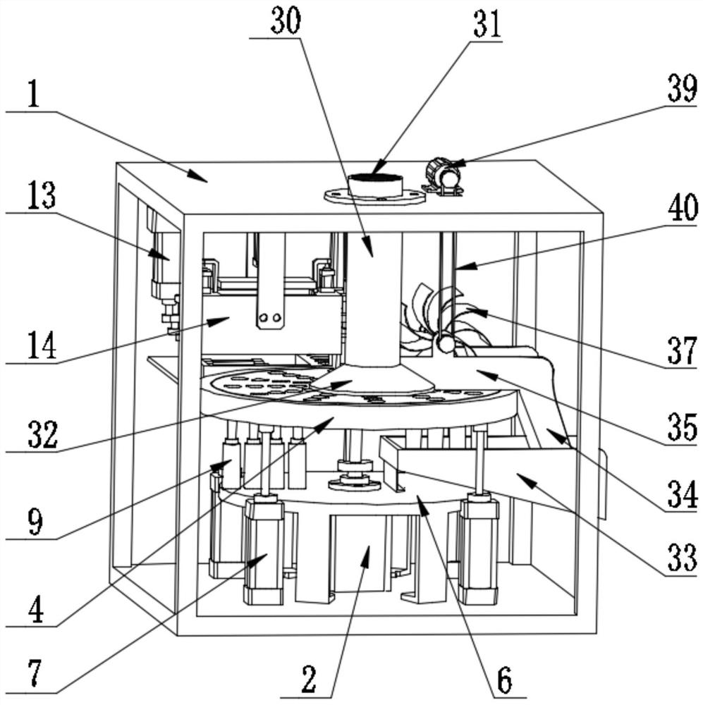
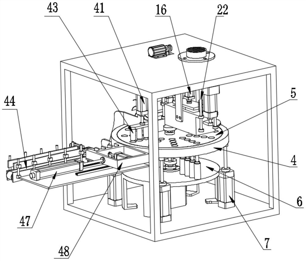
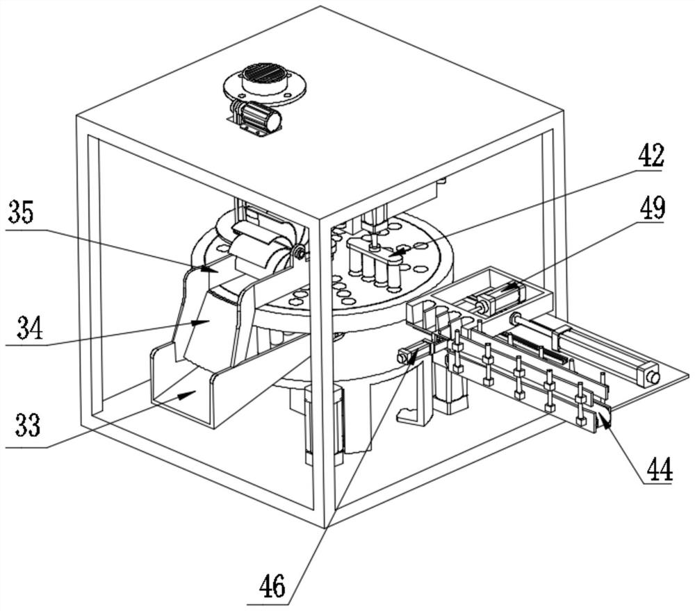
[0054] A kind of commutator automatic compression mold device of the present embodiment, refer to Figure 1-14 : Including the body 1, the inner and lower layers of the middle part of the body 1 are equipped with a transfer compression molding mechanism, which is used to transfer the arranged commutator segment group, transfer the wire change segment group to the compression molding station and perform compression molding into finished products, and transfer the finished products in sequence To the air cooling station and the discharge station;

[0055] The upper left part of the body 1 is equipped with an injection molding mechanism, which is used to inject the hot-melt plastic matrix into the compression molding station to form a finished product;

[0056] An air-cooling mechanism is installed in the upper layer of the front part of the body 1, which is used to cool the finished product by air cooling;

[0057] The middle and lower layer of the right part of the body 1 is e...


PUM


Abstract

The invention relates to the field of commutator compression molds, in particular to a commutator automatic compression mold device. The device comprises a machine body, and a transfer compression molding mechanism is arranged on the lower layer in the middle of the machine body and is used for transferring arranged commutator segment groups, transferring the commutator segment groups to a compression molding station, carrying out compression molding to form finished products and transferring the finished products to an air cooling station and a discharging station in sequence. An injection molding mechanism is arranged in the upper layer of the left portion of the machine body and is used for injecting hot-melt plastic matrixes into the compression molding station to form the finished products. An air cooling mechanism is arranged in the upper layer of the front portion of the machine body and is used for cooling the finished products in an air cooling manner. A discharging mechanism is arranged on the middle lower layer of the right portion of the machine body and is used for removing the finished products from the transfer compression molding mechanism and collecting the finished products in a centralized manner. A commutator segment feeding mechanism is arranged on the rear portion of the machine body, and the arranged commutator segment groups are sequentially put into a segment feeding station. According to the commutator automatic compression mold device, automatic and continuous compression molding is achieved, the compression-molded finished products are automatically discharged, collected and centralized, the compression molding efficiency is improved, and the labor intensity of workers is reduced.

Description

technical field [0001] The invention relates to the field of compression molding molds for commutators, in particular to an automatic compression molding mold device for commutators. Background technique [0002] Generally, the compression molding of traditional commutators requires multiple processes, including taking out and putting the entire compression mold from the press several times, taking off the template, taking off the template, and demoulding the product, all of which are manually operated. , and because the plastic material needs to be heated during compression molding, the heating temperature is generally 180-200°C, and workers must wear thick heat-insulating gloves when operating. The entire operation process is cumbersome, the production efficiency is low, and the labor intensity of the workers is high. [0003] At present, the Chinese patent number "201210066787.2" discloses a commutator compression mold, including an upper template, a middle template, a lo...

Claims


Application Information

Patent Timeline
IPC IPC(8): B29C43/08B29C43/18B29C43/32B29C43/50B29C43/52B29C43/58
CPCB29C43/08B29C43/18B29C43/32B29C43/50B29C43/52B29C43/58B29C2043/503
Inventor 苏光清
Owner 深圳瑞捷金富科技有限公司
Learn More