Fluid dispensing system

A technology of fluid distribution and fluid distributor, applied in the direction of liquid injection device, injection device, pump control, etc., can solve the problem of unfavorable acting as a stopper, the fluid distributor cannot reach the hidden position, etc., to achieve the effect of optimized operation

Active Publication Date: 2021-07-30
法可川斯帕股份公司
View PDF2 Cites 0 Cited by
  • Summary
  • Abstract
  • Description
  • Claims
  • Application Information

AI Technical Summary

Problems solved by technology

However, there may be situations where it is still necessary to activate at least one telescoping fluid dispenser while a particular target object has not been completely cleaned
Therefore, there may be residual fluid that becomes trapped in the telescoping fluid dispenser, which undesirably acts as a stop during the rearward movement of the telescoping fluid dispenser
As a result, the fluid dispenser cannot reach its hidden position

Method used


Image

  • Fluid dispensing system
  • Fluid dispensing system

Examples


Embodiment Construction

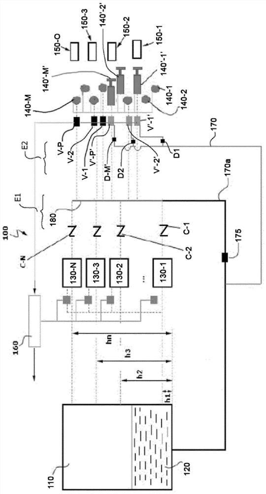
[0079] attached figure 1 One non-limiting example of a fluid distribution system for washing at least a portion of at least one target object 150-1, 150-2, 150-3, . . . , 150-O in a motor vehicle is shown in .

[0080] The fluid distribution system 100 is intended for cleaning the surfaces of components in motor vehicles, ie the surfaces of target objects 150-1, 150-2, 150-3, . . . , 150-O. In the example shown, the target objects 150-1, 150-2, 150-3, . . . , 150-O can be, for example, many different objects, such as lidars, cameras, windshields, sensors, or sensor covers . The target objects 150-1, 150-2, 150-3, . . . , 150-O may have different cleaning requirements depending on their contamination or soiling status, so they may require different amounts of fluid or cleaning fluid 120 in order to be properly cleaned. However, those skilled in the art will readily recognize that applications other than those described herein are of course possible and that multiple fluid di...


PUM


Abstract

The fluid dispensing system (100) comprises at least one fluid source (110), at least one pump (130-1, 130-2, 130-3 to 130-N), at least one telescopic fluid dispenser (140'-1', 140'-2', 140'-3' to, 140'-M'); a control unit (160) to operate the pump (130-1, 130-2, 130-3 to 130-N) for supplying fluid (120) according to a received command of washing at least one target object (150-1, 150-2, 150-3 to150-O), a manifold (180), and at least one control valve assembly (V-1, V-2 to V'-P') comprising a fluid inlet for receiving fluid from the at least one fluid source (110), a first fluid outlet for discharging fluid into the at least one telescopic fluid dispenser (140'-1, 140'-2, 140'-3 to 140'-M'), and a second fluid outlet for allowing fluid to flow back away from the telescopic fluid dispensers (140'-1, 140'-2', 140'-3' to 140'-M') when retracting from the extended position to the rest position.

Description

technical field [0001] This application claims the benefit of European Patent Application EP18382943.1, filed on December 18, 2018. [0002] The present disclosure relates to fluid distribution systems, particularly fluid distribution systems that include telescoping nozzles that deliver liquid into one or more target objects. The fluid distribution system of the present invention is applicable, for example, to cleaning devices for cleaning automotive components, such as optical components, although other applications are not excluded. Background technique [0003] In known fluid distribution systems, fluid is pumped from a tank or reservoir by a suitable pump and discharged towards a target object through a nozzle connected to the pump. [0004] US5190442 discloses an electronic pump control system for ensuring that the pump operates for the same percentage of time. The system includes a container for the liquid, a sensing device for determining the level of the liquid in...

Claims


Application Information

Patent Timeline
Patent Type & Authority Applications(China)
IPC IPC(8): B60S1/52B05B1/28B05B1/30B05B15/656B05B15/70F04D15/00F04D15/02B60S1/48B05B9/03B05B12/08
CPCB05B9/035B05B12/08B60S1/481F04D15/00F04D15/029B05B15/18B05B15/74B60S1/526B05B1/3093B05B1/28B05B15/656B05B15/70
Inventor O·阿尔卡德·赫尔南德斯约瑟·路易斯·比利亚鲁维亚·瓜里诺
Owner 法可川斯帕股份公司
Why Eureka
Try Eureka