A sand and gravel screening device with controllable sieve holes in building construction
A technology for building construction and screening device, which is applied in the fields of sieving, solid separation, chemical instruments and methods, etc., can solve the problems of low efficiency, large occupation area of sand and gravel screening device, and inability to arbitrarily change the size of sand and gravel screening, etc. Achieve the effect of avoiding mesh clogging and improving screening efficiency
- Summary
- Abstract
- Description
- Claims
- Application Information
AI Technical Summary
Problems solved by technology
Method used
Image
Examples
Embodiment 1
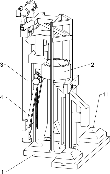
[0036] Please refer to figure 1 As shown in the figure, a sand and gravel screening device with controllable sieve holes in construction, including a bottom plate 1, a separation mechanism 2 and a circulating feeding mechanism 3, a separation mechanism 2 is installed on the top of the bottom plate 1, and the top of the bottom plate 1 on the left side of the separation mechanism 2 is installed A circulating feeding mechanism 3 is provided, and the circulating feeding mechanism 3 is connected with the separating mechanism 2 .
[0037] When the sand and gravel need to be screened, the user places the present invention in a suitable position on the right side of the gravel pile, then the user swings the circulating feeding mechanism 3 to the left, inserts the lower part of the circulating feeding mechanism 3 into the gravel pile, and then The user starts the circulating feeding mechanism 3 to work, and the circulating feeding mechanism 3 works to transport the sand upward to the s...
Embodiment 2
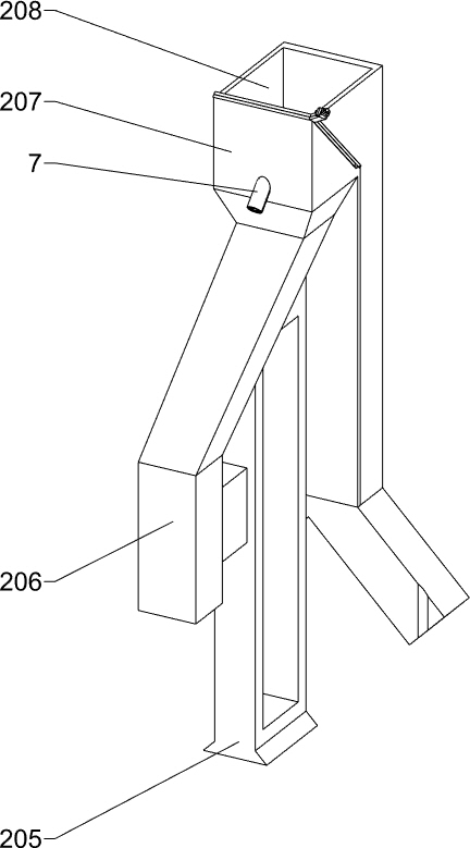
[0039] Please refer to Figure 2-Figure 4 As shown, on the basis of Embodiment 1, the separation mechanism 2 includes a fixed frame 201, a trough-shaped eccentric frame 202, a support frame 205, a first blanking pipe 206, a blanking frame 207, a second blanking pipe 208, a diverter Pipes 2081 and screening components, the fixing frame 201 is connected to the top left side of the bottom plate 1, the upper inner side of the fixing frame 201 is fixed with a grooved eccentric frame 202, and the top of the bottom plate 1 on the right side of the fixing frame 201 is installed with a supporting frame 205, the supporting frame A first unloading pipe 206 is installed on the top of 205, a unloading rack 207 is installed on the top of the first unloading pipe 206, a second unloading pipe 208 is installed on the left side wall of the unloading rack 207, and the second unloading pipe 208 A shunt duct 2081 is installed at the bottom of the duct, and a screening part is arranged between the ...
Embodiment 3
[0044] Please refer to Figure 5-Figure 8 As shown, on the basis of Embodiment 2, the circulating feeding mechanism 3 includes a first support rod 301, a second support rod 3011, a hollow frame 3012, a third support rod 302, a mounting frame 303, a feeding chute 304, a first The reduction motor 305, the first gear 306, the first shaft 307, the second gear 308, the bushing 309, the first bearing seat 310, the second bearing seat 311, the connecting frame 312, the first bevel gear 313 and the feeding part, the first There are two support rods 301, and the two first support rods 301 are fixed on the front and rear sides of the top of the bottom plate 1. The front and rear first support rods 301 are located between the fixed frame 201 and the support frame 205. The support frame 205 A second support rod 3011 is installed on the top of the bottom plate 1 on the front and rear sides, a hollow frame 3012 is fixed between the upper ends of the two front and rear second support rods 30...
PUM
 Abstract
Description
Claims
Application Information
 - R&D
- Intellectual Property
- Life Sciences
- Materials
- Tech Scout
- Unparalleled Data Quality
- Higher Quality Content
- 60% Fewer Hallucinations
Browse by: Latest US Patents, China's latest patents, Technical Efficacy Thesaurus, Application Domain, Technology Topic, Popular Technical Reports.
© 2025 PatSnap. All rights reserved.Legal|Privacy policy|Modern Slavery Act Transparency Statement|Sitemap|About US| Contact US: help@patsnap.com


