Energy-saving and environment-friendly gasket cutting equipment

An energy-saving, environmentally friendly, gasket technology, applied in metal processing, household components, other household appliances, etc., can solve the problem of gaskets becoming waste, unable to guarantee edge parts, etc., to achieve the effect of easy trimming work

Active Publication Date: 2021-08-03
HEBEI HUATONG HEAVY IND MACHINERY MFG CO LTD
View PDF5 Cites 1 Cited by
  • Summary
  • Abstract
  • Description
  • Claims
  • Application Information

AI Technical Summary

Problems solved by technology

[0004] Aiming at the disadvantage that the edge of the gasket cannot be guaranteed to be still round during manual cutting, so that the gasket becomes a waste product, it is necessary to provide an energy-saving and environmentally friendly gasket cutting equipment that does not require manual cutting and keeps the edge of the gasket after cutting round.

Method used


Image

  • Energy-saving and environment-friendly gasket cutting equipment
  • Energy-saving and environment-friendly gasket cutting equipment
  • Energy-saving and environment-friendly gasket cutting equipment

Examples


Embodiment 1

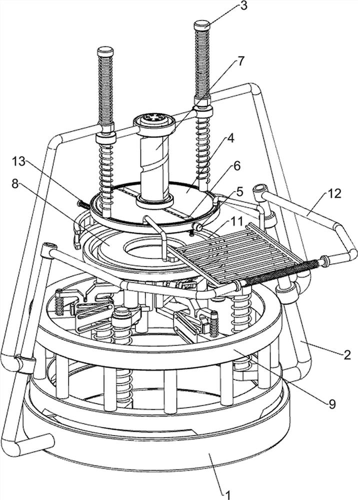
[0024] A kind of energy-saving and environment-friendly gasket cutting equipment, refer to figure 1 As shown, it includes a base 1, a first mounting rod 2, a guide rod 3, a mounting plate 4, a worm 5, a cutting tool 6, a trimming mechanism 7 and a placement mechanism 8, and the left and right sides of the base 1 are provided with a first mounting rod 2. , the trimming mechanism 7 is connected between the first mounting rods 2, the trimming mechanism 7 parts are slidingly provided with guide rods 3, the bottoms of the guiding rods 3 are slidingly connected with mounting discs 4, and the middle part of the mounting discs 4 is rotatably provided with a worm 5. A cutting tool 6 is threaded on the worm 5 , and a placement mechanism 8 is provided on the top of the base 1 .

[0025] refer to figure 2 As shown, the trimming mechanism 7 includes a second mounting rod 71, a first spring 72, a second spring 73, a force plate 74, a groove tube 75 and a lower pressing rod 76, and the low...

Embodiment 2

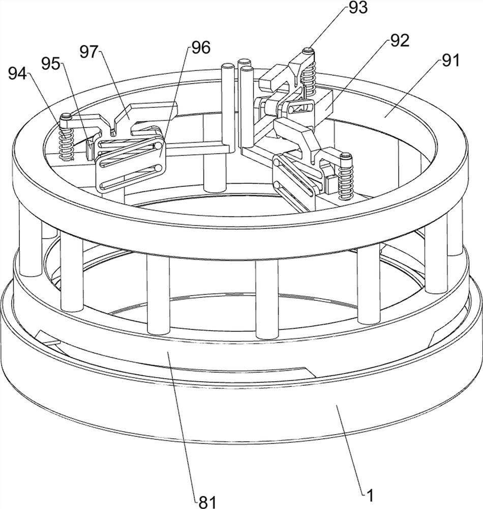
[0029] On the basis of embodiment 1, refer to Figure 4 As shown, it also includes a spreading mechanism 9, and the spreading mechanism 9 includes a spreading frame 91, a second mounting block 92, a first guide post 93, a fourth spring 94, a slide block 95, a slide plate 96 and a pressing plate 97, and the placement frame The top of 81 is provided with a stretching frame 91, and the inner side of the stretching frame 91 is evenly provided with three second mounting blocks 92, and the top of the second mounting block 92 is provided with a first guide column 93, and the sliding type on the first guiding column 93 is provided with a slide block 95 , the inner side of the slider 95 is provided with a pressure plate 97, the fourth spring 94 is connected between the pressure plate 97 on the same side and the first guide column 93, and two slide plates 96 are arranged on the inner side of the second mounting block 92, and the slide plate on the same side 96 and the pressing plate 97 ...


PUM


Abstract

The invention relates to cutting equipment, in particular to energy-saving and environment-friendly gasket cutting equipment. Aiming at the defects in the prior art, the energy-saving and environment-friendly gasket cutting equipment which does not need manual cutting work and keeps the edge of a cut gasket round is provided. The energy-saving and environment-friendly gasket cutting equipment comprises a base, first mounting rods, guide rods, a mounting disc, a worm, a cutting tool, a trimming mechanism and a placing mechanism, the first mounting rods are arranged on the two sides of the base; the trimming mechanism is connected between the first mounting rods; the guide rods are slidably arranged on a trimming mechanism part; the mounting disc is slidably connected between the bottoms of the guide rods; the worm is rotatably arranged in the middle of the mounting disc; the cutting tool is arranged on the worm in a threaded mode; and the placing mechanism is arranged on the top of the base. The position of the cutting tool can be adjusted through the arranged worm, so that various gaskets can be trimmed.

Description

technical field [0001] The invention relates to a cutting device, in particular to an energy-saving and environment-friendly gasket cutting device. Background technique [0002] Gaskets are widely used in automobile, electronics, chemical industry, antistatic, flame retardant, food, various mechanical equipment and other industries, and can play the role of gasket, seal, buffer and so on. [0003] Gaskets are usually circular. After the gasket is produced, there are usually some defective products with rough edges. Therefore, it is necessary to cut the edge. Usually, the gasket is placed manually first, and the edge of the gasket is cut with a cutter. Cutting work removes the rough part, but manual cutting cannot guarantee that the edge part is still round, so that the gasket becomes a waste product, so it is necessary to design a gasket that does not need manual cutting work, and the edge of the gasket after cutting remains round. Energy-saving and environmentally friendly...

Claims


Application Information

Patent Timeline
Patent Type & Authority Applications(China)
IPC IPC(8): B26D1/12B26D7/01B26D7/02B26D7/14B26D7/26B26D7/06B29C37/02B29L31/26
CPCB26D1/12B26D7/01B26D7/02B26D7/14B26D7/2628B26D7/2614B26D7/06B29C37/02B29L2031/265B29L2031/7098Y02P70/10
Inventor 吴昆
Owner HEBEI HUATONG HEAVY IND MACHINERY MFG CO LTD
Why Eureka
Try Eureka