a vaginal dilator

A technique of vaginal dilator and vaginal opening, which is applied in colposcopy, obstetrics and gynecology equipment, and ovulation diagnosis, etc. It can solve the problems of sampling deviation, occupancy, and increased work of doctors, so as to shorten the operation time and improve work efficiency. The effect of reducing discomfort and

Active Publication Date: 2022-01-11
深圳市保安医疗用品有限公司
View PDF23 Cites 1 Cited by
  • Summary
  • Abstract
  • Description
  • Claims
  • Application Information

AI Technical Summary

Problems solved by technology

[0004] The above-mentioned invention applies the colposcope and LED lights to the vaginal dilator, and the patient’s cervical image can be directly received from the computer without the doctor holding the colposcope. However, the above-mentioned setting still has the following deficiencies in practical application: 1. The vaginal device is a disposable medical consumable, and the vaginal environment of the patient is different, and the pathogenic bacteria carried in it is unknown. If the above-mentioned vaginal dilator is a disposable product, the built-in electronic controller will be expensive, resulting in The significant increase in the cost of the entire vaginal dilator will significantly increase the cost of the patient, and the application prospect is not promising; 2. In the gynecological examination, it is necessary to collect samples. The existing operation is that the doctor directly holds the cotton swab and stretches it. Into the inside of the vaginal dilator without a colposcope, and take a sample by touching the cotton swab to the patient's cervix by feeling, which may lead to sampling deviations, that is, samples from the disease-causing area are not collected, which affects the follow-up treatment of the patient, and manual sampling is time-consuming It is laborious and increases the work of the doctor. Although the vaginal speculum of the above comparative literature can be sampled with the help of images, because the colposcope itself occupies the internal space of the vaginal speculum, it will increase the difficulty of manual sampling and will significantly prolong the time for a single patient. The treatment time of the patient is reduced, and the work efficiency of the doctor is reduced

Method used


Image

  • a vaginal dilator
  • a vaginal dilator
  • a vaginal dilator

Examples


Embodiment

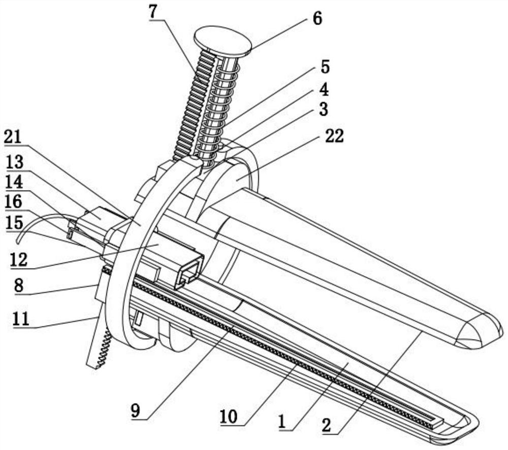
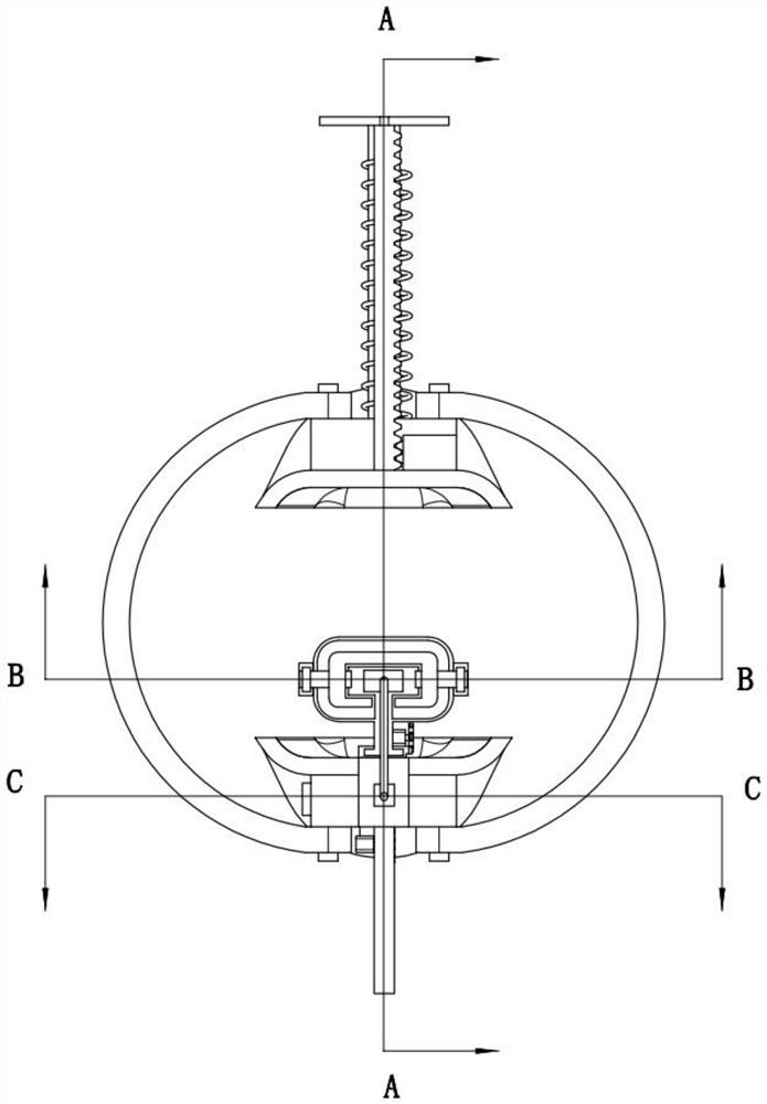
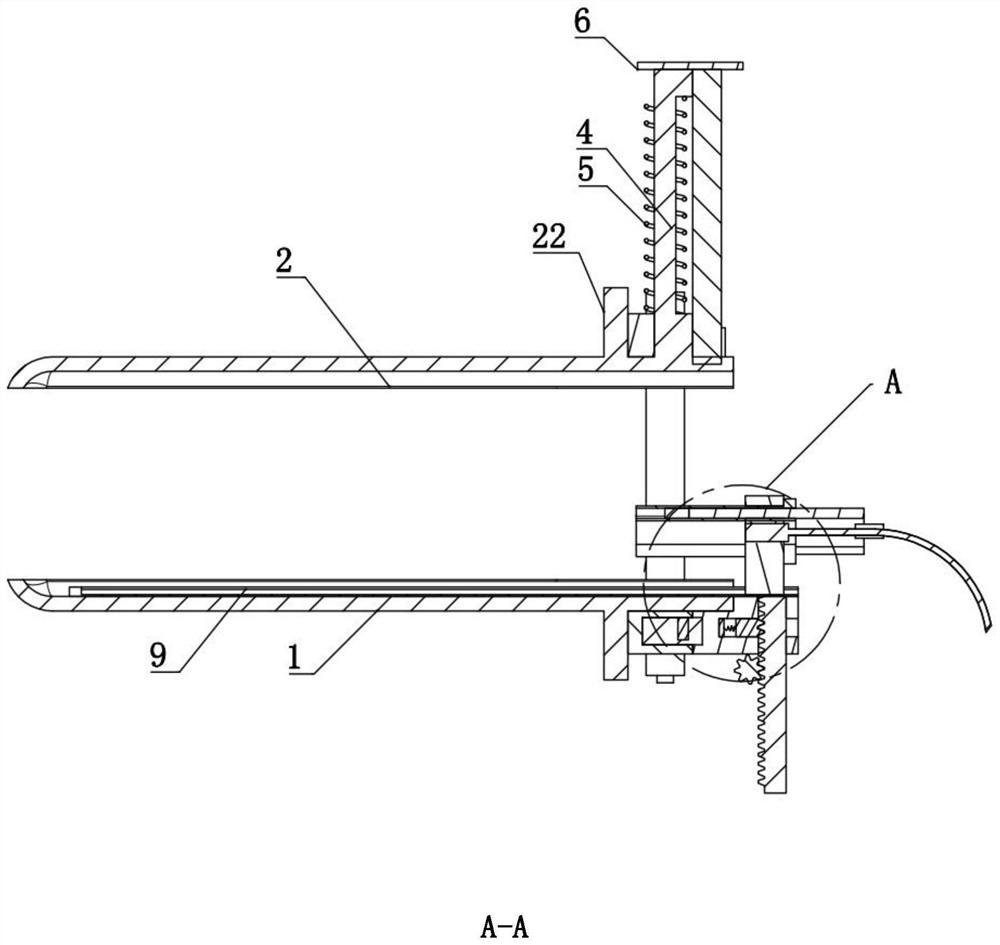
[0035] A vaginal speculum combined with Figure 1-Figure 11 , including the main body of the vaginal speculum, first refer to Figure 1-Figure 4As shown, the vaginal dilator main body includes a lower support piece 1, an upper support piece 2 arranged up and down above the lower support piece 1, and an end of the upper support piece 2 far away from the vaginal opening, which is connected to the lower support piece 1 and can drive the upper support piece. The first drive mechanism for lifting and locking the sheet 2, on the opposite side of the upper supporting sheet 2 and the lower supporting sheet 1, extends vertically to limit the limit block 22 at the end far away from the vaginal opening, and on the side of the lower supporting sheet 1 away from the vaginal opening One end is detachably fixed with an image acquisition mechanism and an automatic sampling mechanism. The image acquisition mechanism includes a fixed block 8 detachably fixed on the lower support piece 1, a guid...


PUM


Abstract

The invention relates to the field of medical instruments, and discloses a vaginal dilator for gynecological surgery, which includes a vaginal dilator main body. The first driving mechanism that lifts and locks the lower support piece, and the image acquisition mechanism and automatic sampling mechanism are detachably fixed on the end of the lower support piece away from the vaginal opening. The image acquisition mechanism includes a fixed block, a guide rail, and The second driving mechanism that is set to drive the guide rail to lift and lock is guided above the guide rail with a bracket that is equipped with a colposcope and an LED light. Three driving mechanisms, the image acquisition mechanism and the automatic sampling mechanism on the dilator can be disassembled and can realize the peeping of the internal situation of the vagina and the automatic sampling of the cervix in the peeping state, which significantly improves the sampling accuracy and reduces the cumbersomeness of the operation .

Description

technical field [0001] The invention relates to the field of medical instruments, in particular to a vaginal dilator. Background technique [0002] At present, doctors mainly rely on vaginal dilators and colposcopes to examine gynecological patients. The vaginal dilators are used to dilate the vagina. Under the irradiation of external light sources, doctors can examine the cervix. The colposcope must be used with the help of vaginal dilators. The best method of use is to first open the vagina with a vaginal dilator, place the colposcope at a certain distance outside the vagina, and observe, photograph and collect images of the patient's vagina with the help of an external light source. The above-mentioned application of the colposcope has the following disadvantages. The doctor needs to hold the colposcope while observing the images fed back by the colposcope in the computer to find the lesions, which is inconvenient for the doctor to use and consumes more energy. [0003] ...

Claims


Application Information

Patent Timeline
Patent Type & Authority Patents(China)
IPC IPC(8): A61B17/02A61B17/42A61B90/30A61B10/04A61B1/303A61B1/04A61B1/06
CPCA61B17/0206A61B17/42A61B90/30A61B10/04A61B10/0045A61B1/303A61B1/04A61B1/0684A61B2090/309A61B2010/0074
Inventor 吴昊吴婷吴征飞张明玉
Owner 深圳市保安医疗用品有限公司
Why Eureka
Try Eureka