Lifesaving device with auxiliary rescue function
A technology of life-saving devices and functions, which is applied in the field of life-saving devices with auxiliary rescue functions, which can solve the problems of violent shaking of the hull, capsizing, time-consuming and labor-intensive problems, and achieve the effect of avoiding shaking or rollover
- Summary
- Abstract
- Description
- Claims
- Application Information
AI Technical Summary
Problems solved by technology
Method used
Image

Examples
Embodiment 1
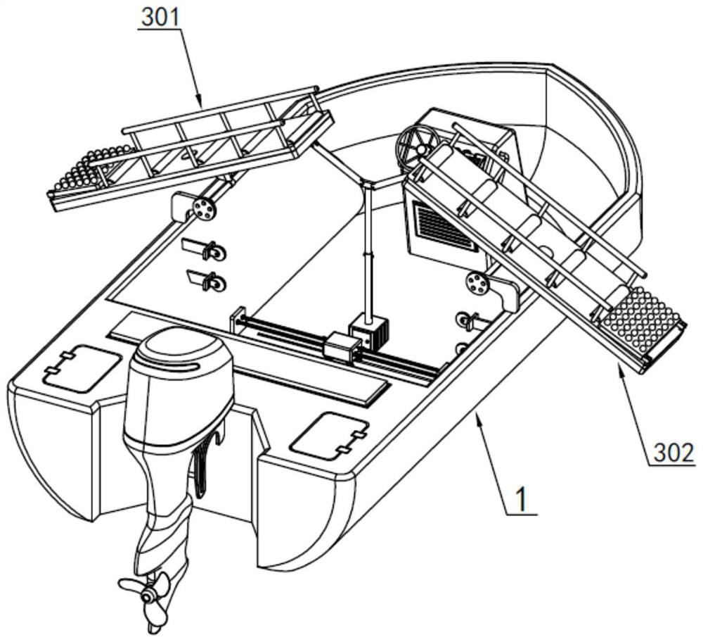
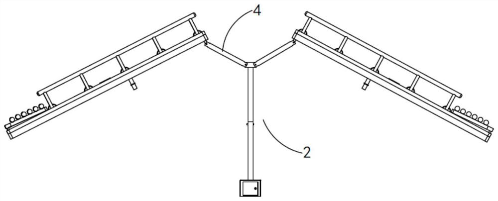
[0036] Such as Figure 1 to Figure 12As shown, a life-saving device with its own auxiliary rescue function includes a lifting assembly 2 arranged on the hull 1, and a first bearing mechanism 301 and a second bearing mechanism 302 are provided on both sides of the hull 1 to rotate on the edge. The first load-bearing mechanism 301 and the second load-bearing mechanism 302 are used to provide load-bearing support for people falling into the water, and the lifting assembly 2 is hinged to the first load-bearing mechanism 301 and the second load-bearing mechanism 302 through the connecting rod 4. The first carrying mechanism 301 and the second carrying mechanism 302 are turned over under the drive of the lifting assembly 2 to lift the carried person into the water out of the water, and the first carrying mechanism 301 and the second carrying mechanism 302 are provided with a rotating assembly 5 , the rotating assembly 5 rotates to cooperate with rescuers to transfer the drowning per...
Embodiment 2
[0048] Such as Figure 13 As shown, the parts that are the same as or corresponding to those in Embodiment 1 adopt the reference numerals corresponding to Embodiment 1. For the sake of simplicity, only the differences between Embodiment 1 and Embodiment 1 are described below; the differences between Embodiment 2 and Embodiment 1 The difference is that: the rotating assembly 5 includes a rotating column 501 arranged on the bearing bottom plate 305, the top of the rotating column 501 is provided with a limit support block 502, and the rotating column 501 is provided with a bearing rotating plate 503.
[0049] It should be pointed out that the present invention cooperates with the locking assembly 8 provided with the rotating assembly 5, and when the carrying mechanism carries and supports the person who fell into the water to be lifted out of the water, the latch 803 on the locking assembly 8 is inserted into the latch seat a801 and the latch seat b802 thus locks the load-beari...
PUM
 Abstract
Description
Claims
Application Information
 - R&D
- Intellectual Property
- Life Sciences
- Materials
- Tech Scout
- Unparalleled Data Quality
- Higher Quality Content
- 60% Fewer Hallucinations
Browse by: Latest US Patents, China's latest patents, Technical Efficacy Thesaurus, Application Domain, Technology Topic, Popular Technical Reports.
© 2025 PatSnap. All rights reserved.Legal|Privacy policy|Modern Slavery Act Transparency Statement|Sitemap|About US| Contact US: help@patsnap.com