[0018] Next, the technical solutions in the embodiments of the present invention will be apparent from the embodiment of the present invention, and it is clearly described, and it is understood that the described embodiments are merely embodiments of the present invention, not all of the embodiments. Based on the embodiments of the present invention, there are all other embodiments obtained without making creative labor without making creative labor premises.
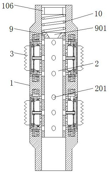
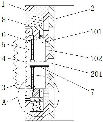
[0019] See Figure 1-4 A hydraulic anchor for the hydraulic well-sand cracking operation, including the hydraulic anchor pipe 1, the top and bottom of the outer side of the hydraulic anchor body tube 1 are opened with four kara holes 101, and the hydraulic anchor main pipe 1 Both of the four karvile grooves 101 are symmetrically symmetrical in the axial center of the hydraulic anchor body tube 1, and the hydraulic anchor main body tube 1 is fixedly connected to a defined plate strip 4 on the outer side of the karva groove 101, and the defined plate strip is located in the Kava The middle of the groove 101, the internal activity set of the karva groove 101 has a sliding plate 5, and the outer side of the slide plate 5 is completely bonded, and the side surface of the ferric tank 101 is fixedly connected to the defined plate strip 4 two. The anchor 3, and the outer side of the anchor 3 and the inner wall of the karvile groove 101, and the defined plate strip 4 and the slide plate 5 are provided with a rubber seal sleeve 6, hydraulic. The anchor body tube 1 fixing a set of positioning pipe 7 located at the inner side wall of the karva groove 101, the positioning pipe 7 and the sliding plate 5 active jack, and the positioning pipe 7 is positioned to turn on the lumen of the rubber seal sleeve 6 and The central inner cavity of the hydraulic anchor body tube 1, and the hydraulic anchor body tube 1 is also opened to two anchored water holes 102 on both sides of the positioning pipe 7, and an anchored water hole 102 is connected to the ferrule groove 101 The middle cavity of the cavity and hydraulic anchor body tube 1, the central lumen activity set of the hydraulic anchor body tube 1, the intermediate sleeve 2 is only longitudinally moving in the hydraulic anchor main pipe 1, and the intermediate sleeve 2 The outer side is bonded to the inner wall of the hydraulic anchor body tube 1, and eight sets of guiding holes 201 are opened on the intermediate sleeve 2, each of which corresponds to one kara slot 101, and the number of each set of airflow holes 201 is Three, and each of the three passage holes 201 each other is equal to the intermediate sleeve 2, and the top fixed set of the hydraulic anchor main pipe 1 in the middle cavity is located above the intermediate sleeve 2, the intermediate sleeve The top end fixing set of the tube 2 has a linkage block 9, and the middle portion of the linkage block 9 is opened, and the inner diameter of the throttle groove 901 is uniform, and the inner diameter value of the positioning ring 106 is greater than the throttle groove 901. The maximum outer diameter value is provided between the top portion of the linkage block 9 and the bottom of the positioning ring 106, and the tension of the tension spring 10 is used, and the intermediate of each set of airflow holes 201 is present in the middle of each set of airflow holes 201. Located at the positioning pipe 7, the inner cavity of the intermediate sleeve 2 is turned on and the lumen of the rubber sealing sleeve 6 is turned on.
[0020] When the sand fracturing operation is performed, when the pillar is anchored, the pitch falls into the hydraulic anchor body tube 1, and the water is continuously injected, the injected water flow flows through the throttle groove 901, led linkage The block 9, the intermediate sleeve 2 is moved, so that the flow hole 201 is moved to an anchored water hole 102, and the water in the hydraulic anchor main pipe 1 is not over the flow of the flow hole 201, the water flows through the flow of flow through the guide hole 201. The kaisha groove 101 is left to move the slide plate 5, the anchor shield 3, so that the side of the anchor 3 is removed from the outside of the hydraulic anchor body tube 1 and the inner wall of the sleeve, thereby achieving anchoring, and After all the anchor 3 is anchored, the water flow of the water disappear, under the pulling force of the tensile spring, so that the linkage block 9, the intermediate sleeve 2 is reset, at this time, the flow hole 201 is moved to the positioning pass. At the pipe 7, the anchored into the aperture 102 is in a state of being blocked by the intermediate sleeve 2, and the anchor 3 is maintained at an anchoring state under the water pressure of the ferric tank 101, so that the anchor 3 is held in an anchor state without maintaining a hydraulic anchor body. The state of the tube 1, thereby effectively reducing energy consumption, after the fracturing operation is completed, the water flow passes through the throttle 901, not enough to drive the joint block 9, the intermediate sleeve 2 overall downward The water flow in the hydraulic anchor main pipe 1 is passed into the rubber sealing sleeve 6 in the water flow hole 201, and the sliding plate 5 is moved to the right as the water flow continues to move, so that the anchor 3 The sliding plate 5 is moved to the kaisha slot 101, unniposter, throughout the process, by anchoring and contacting anchoring and contacting anchoring, compared to the existing hydraulic anchor utilizing the elasticity of the spring. For the purpose of unnipating the anchor, it is effective to avoid the anchor 3. The spring is not enough to solve the card, thereby causing a card diamond accident.
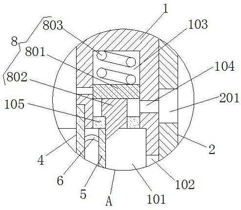
[0021]The hydraulic anchor main pipe 1 is opened to the chute 103 on both sides of the karvile groove 101, and the inner cavity of the two chute holes 103 is connected to the lumen of the ferrous groove 101, and a card is provided in the chute 103. The mechanism 8, the labary mechanism 8 includes a movable sleeve 801, and the bottom of the piston plate 801 is fixedly connected to the piston 802, and the bottom end of the card shaft 802 is a bevel design, and the top and sliding of the piston plate 801 A spring 803 is provided between the top inner wall of the groove 103, the bottom sealing sleeve set of the chute 103, with a sealing block 105, and the top diameter of the card shaft 802 is larger than its bottom diameter, and the bottom of the card shaft 802 and the sealing block 105 active socket, hydraulic force The anchor main body tube 1 is opened, and the outer portion of the drainage groove is connected to the hydraulic anchor body tube 1, and the hydraulic anchor body tube 1 is also opened to the aqueous hole 104 below the piston plate 801, and The anchor anchor into a state in which the flow hole 201 is in communication with the guide hole 201, and the inside of the intermediate sleeve 2 is turned on, in the anchoring engine, the sliding plate 5 is driven under the anchoring engine. The anchor 3 moves to the outside of the kaisha groove 101, and the sliding plate 5 moves the bevel of the card shaft 802, so that the card shaft 802 is moved to the slide plate 5 to be moved to one side of the card shaft 802, the card shaft 802 is in the spring The slide plate 5 is inserted under the elastic action of 803, so that the sliding plate 5 maintains a stable state, thereby so that the anchored anchor hilar 3 maintains a stable state, which is effective to avoid the existing hydraulic anchor. Due to the need for a water pressure to keep the pressure such that the anchor 3 remains anchored, it is easy to affect the pressure of the anchoring, so that the anchoring effect is poor, resulting in anchoring effect. Good, affecting the problem of subsequent construction, when the anchor is canceled, the water flow is slowly injected, so that the water flow passes through the throttle 901, it is not sufficient to drive the joint block 9, the intermediate sleeve 2 is moved down, and the water flows into the sealing block through the flow through the flow hole 201. 105. Inside the positioning pipe 7, as the water pressure increases, the inner piston plate 801 is separated from the sliding plate 5 to the sliding plate 5, and the water is flowed into the rubber sealing sleeve 6 through the positioning pipe 7. Inside, the rubber sealing sleeve 6 is expanded, and the slide plate 5 is moved toward the inner side of the kaisher groove 101, so that the anchor 31 is moved to the karvile groove 101, thereby canceling anchoring, and the karva groove 101 The water in the water through the gap between the card shaft 802 and the sealing block 105, the drain tank flows out, by slow injection, the anchor 3 is moved to the ferric 101, compared to the existing hydraulic anchor utilization When the spring arm force is released, it is easy to solve the problem of smashing the efficiency of the sand cracking effect due to the limited elastic force of the spring.
[0022] When used, the hydraulic anchor tube 1 is placed to the job of the crack layer, and then the pitch will fall into the hydraulic anchor main pipe 1, after the jacket is sealed, the water flows, the injected water flow flows through the throttle 901 The joint block 9, the intermediate sleeve 2 is moved, so that the fluid hole 201 is moved to an anchored water hole 102, and the water in the hydraulic anchor main pipe 1 is not over the flow of the flow, into the water flow through the flow 201 flows to the kaisha groove 101, thereby moving the sliding plate 5, the anchor 3, so that the side of the anchor shield 3 removes the outer portion of the hydraulic anchor body tube 1 and snaps to the inner wall of the sleeve, thereby performing anchor Declats, after the water injection pressure disappears, the linkage block 9, the intermediate sleeve 2 is moved, so that the three guide holes 201 each group is positioned with the positioning pipe 7, sealing block 105, respectively. The inner cavity is connected. When the anchor is canceled after the operation, slow water in the hydraulic anchor main pipe 1, the water flows into the sealing block 105 in the flow of the flow hole 201, and the pipe 7 is positioned, with the increase of water pressure In order to cause the inner piston plate 801 to be separated from the slide plate 5, the water is flowed into the rubber sealing sleeve 6 in the positioning pipe 7, so that the rubber sealing sleeve 6 expands, drives the slide plate 5, The anchor shield 3 moves toward the inside of the kaar groove 101 such that the anchor 3 is moved to the karvile groove 101, thereby canceling the anchor, and the water in the ferrous groove 101 and the gap between the card shaft 802 and the sealing block 105. The drain groove is flowing out.
[0023] It should be noted that in this article, a relationship term such as the first and second, etc. is only used to separate an entity or operation with another entity or an operational area, without having to require or imply these entities or operations. There is any such practical relationship or order. Moreover, the term "comprising", "comprising" or any other variable is intended to encompass non-exclusive contained, so that the process, method, article, or device including a series of elements, not only those elements, but also not expressly listed. Other elements, or elements that are also inherent to this process, method, item, or device.
[0024] While the embodiments of the invention have been shown and described, these examples may be made to make a variety of changes, modifications, and replacement without departing from the principles and spirit of the present invention, without departing from the spirit and spirit of the present invention. And variations, the scope of the invention is defined by the appended claims and their equivalents.