Optical-mechanical structure of head-up display system and assembling method of glued lens group of optical-mechanical structure

A head-up display system and gluing mirror technology, applied in installation, optics, projection devices, etc., can solve the problems of reduced brightness, inability to install small and medium-sized cars, and inability to obtain a larger field of view, so as to ensure brightness and clarity and avoid The surface shape of the lens changes, which is beneficial to the overall cooling effect

Active Publication Date: 2021-08-06
CHANGCHUN INST OF OPTICS FINE MECHANICS & PHYSICS CHINESE ACAD OF SCI
View PDF10 Cites 0 Cited by
  • Summary
  • Abstract
  • Description
  • Claims
  • Application Information

AI Technical Summary

Problems solved by technology

W-HUD is widely used in aircraft, especially fighter jets, but because it is very expensive, its application in the automobile and ship industries is very limited. In the automotive industry, it can only be matched with high-end cars.
Currently, the cheap head-up display products available on the market are C-HUD projected on a separate small screen instead of W-HUD on the windshield glass. Although these products are cheap, they cannot be integrated with cars or ships. existing
Moreover, both the HUD products mounted on high-end cars and the independent HUD products on the market have many shortcomings: because the existing W-HUDs are all reflective optical designs, the reflective optical design is limited by the size of the reflector and cannot A larger field of view is obtained, and the resolution of the existing reflective W-HUD is low, and the image is blurred; in addition, the existing reflective W-HUD cannot achieve long-distance projection. The field of view, HUD generally needs to be designed with multiple reflections. Multiple reflections will also cause brightness reduction and lower image information clarity. Moreover, the multiple reflection structure will cause the entire HUD to be very large and cannot be installed in small and medium-sized cars. , the scope of use is relatively limited

Method used


Image

  • Optical-mechanical structure of head-up display system and assembling method of glued lens group of optical-mechanical structure
  • Optical-mechanical structure of head-up display system and assembling method of glued lens group of optical-mechanical structure
  • Optical-mechanical structure of head-up display system and assembling method of glued lens group of optical-mechanical structure

Examples


Embodiment Construction

[0034] The following description serves to disclose the present invention to enable those skilled in the art to carry out the present invention. The preferred embodiments described below are only examples, and those skilled in the art can devise other obvious variations. The basic principles of the present invention defined in the following description can be applied to other embodiments, variations, improvements, equivalents and other technical solutions without departing from the spirit and scope of the present invention.

[0035]Those skilled in the art should understand that, in the disclosure of the present invention, the terms "vertical", "transverse", "upper", "lower", "front", "rear", "left", "right", The orientations or positional relationships indicated by "vertical", "horizontal", "top", "bottom", "inner", "outer", etc. are based on the orientation or positional relationship shown in the drawings, which are only for the convenience of describing the present inventio...


PUM


Abstract

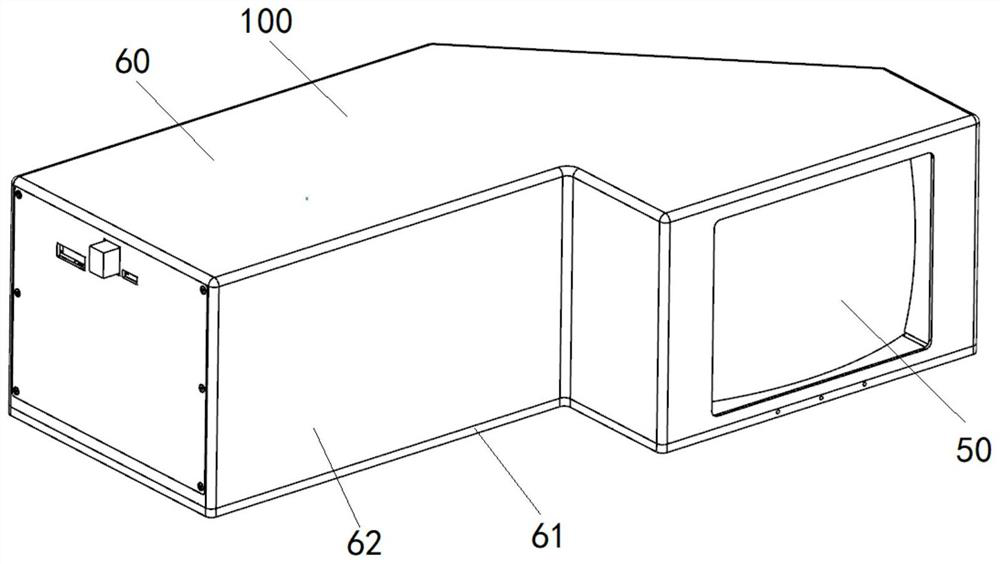
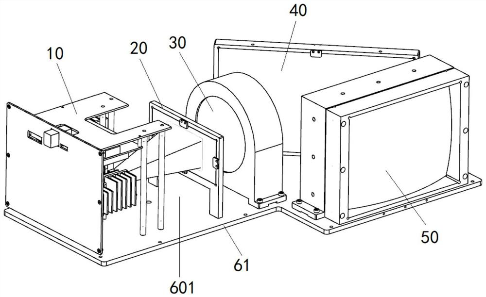
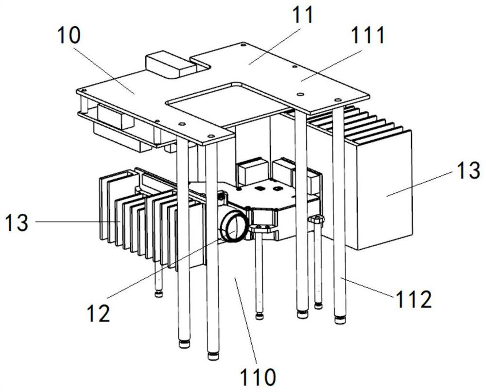
The invention relates to an optical-mechanical structure of a head-up display system and an assembling method of a glued lens group of the optical-mechanical structure of the head-up display system, and the optical-mechanical structure of the head-up display system comprises a projector unit, and a diffusion sheet assembly, a circular transmitting mirror assembly, a reflecting mirror group and the glued lens group which are sequentially arranged on a projection light path of the projector unit, the optical-mechanical structure of the head-up display system adopts a transmission-type optical path design, obtains a larger view field surface, realizes a longer projection distance, shortens the optical path and reduces the dimension by setting a turn-back optical path, avoids energy loss caused by multiple reflections, and ensures the brightness and definition of a projected image.

Description

technical field [0001] The invention relates to the technical field of optical precision mechanical structures, in particular to an optical-mechanical structure of a large-field-of-view transmissive head-up display system and an assembly method of a glued mirror group. Background technique [0002] The head-up display system is referred to as W-HUD (Windshield HUD), also known as the parallel display system, which refers to the driver-centered, blind-operated, multi-functional instrument panel. The function of the head-up display system is to project important information such as speed and navigation onto the windshield in front of the driver, so that the driver can see important driving information such as speed and navigation without looking down or turning his head. W-HUD is widely used in aircraft, especially fighter jets, but because it is very expensive, its application in the automobile and ship industries is very limited. In the automotive industry, it can only be ma...

Claims


Application Information

Patent Timeline
Patent Type & Authority Applications(China)
IPC IPC(8): G02B27/01G03B21/16G02B7/00G02B7/02G02B7/182
CPCG02B27/0101G02B27/0149G03B21/16G02B7/00G02B7/02G02B7/026G02B7/182G02B2027/0169
Inventor 付金宝马俊林张洪文
Owner CHANGCHUN INST OF OPTICS FINE MECHANICS & PHYSICS CHINESE ACAD OF SCI
Why Eureka
Try Eureka