Box-sharing type column switch and incoming and outgoing line sleeve thereof
An on-column switch and co-box technology, which is applied in the field of co-column post switches and their inlet and outlet bushings, can solve the problems of reducing the safe insulation distance inside the box, and achieve the effect of improving the flow capacity and facilitating installation.
- Summary
- Abstract
- Description
- Claims
- Application Information
AI Technical Summary
Problems solved by technology
Method used
Image
Examples
Embodiment 1
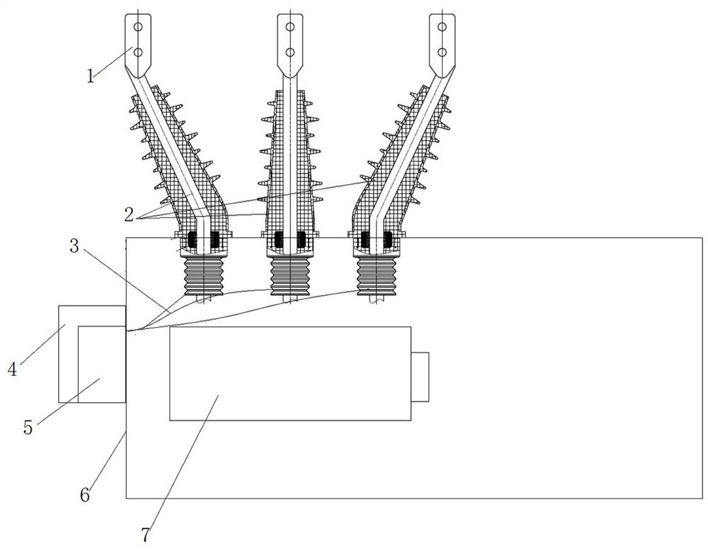
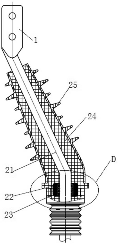
[0064] In the common box-type column switch provided in this embodiment, a voltage sensor 22 is directly integrated and installed in the inlet and outlet bushing 2, and the voltage sensor 22 itself does not need to be provided with an insulation vertical. The insulating resin layer 24 on the 2 is used as a protection, and the power-taking of the high-voltage side of the voltage sensor 22 is completed in the insulating resin layer 24, and only the secondary lead-out wire 3 is drawn out. Compared with the switch box body, the secondary lead wire 3 is a low-voltage lead wire, which will not affect the insulation distance inside the switch box body 6, and can effectively improve the safety of the common-box type pole switch.
[0065] The structure of the common box type column switch is as follows: Figure 2 to Figure 4 As shown, the common box-type pole switch in this embodiment includes a switch box body 6, and a switch function unit 7 is arranged inside the switch box body 6, w...
specific Embodiment 2
[0077] The main difference between it and Embodiment 1 is that in Embodiment 1, the voltage sensor and the central conductive rod are arranged concentrically, which is convenient for arranging the mold during pouring. In this embodiment, a perforation is set eccentrically on the voltage sensor, and a spring contact finger is also installed in the perforation. The rods are arranged eccentrically as a whole, which can be realized by adjusting the position of the supporting mold during pouring.
specific Embodiment 3
[0079] The main difference between it and Embodiment 1 is that in Embodiment 1, the voltage sensors are set outside the conductive rods at intervals. In this embodiment, the voltage sensor can also be arranged on the side of the conductive rod as a whole. At this time, the conductive connection between the high-voltage side of the voltage sensor and the conductive rod can be realized through the built-in high-voltage wire. When installing, it can be machined on the conductive rod. Groove, the connection section of the high-voltage wire is put into the groove correspondingly, and the high-voltage wire and the conductive rod are fixedly assembled together by means of welding connection or screw connection. At this time, the high-voltage wire is also integrally cast and fixed on the insulating resin layer In the same way, it will not affect the insulation distance inside the switch box.
PUM
 Abstract
Description
Claims
Application Information
 - R&D
- Intellectual Property
- Life Sciences
- Materials
- Tech Scout
- Unparalleled Data Quality
- Higher Quality Content
- 60% Fewer Hallucinations
Browse by: Latest US Patents, China's latest patents, Technical Efficacy Thesaurus, Application Domain, Technology Topic, Popular Technical Reports.
© 2025 PatSnap. All rights reserved.Legal|Privacy policy|Modern Slavery Act Transparency Statement|Sitemap|About US| Contact US: help@patsnap.com


