Test tube sterilization and disinfection device

A technology of sterilization and disinfection device and test tube, which is applied in the direction of disinfection, water supply device, sanitary equipment for toilets, etc. It can solve the problems of low cleaning efficiency and achieve the effect of avoiding left and right swinging

Pending Publication Date: 2021-08-10
范桂花
View PDF0 Cites 1 Cited by
  • Summary
  • Abstract
  • Description
  • Claims
  • Application Information

AI Technical Summary

Problems solved by technology

[0004] In order to overcome the shortcomings of the existing test tube brushes with low scrubbing efficiency, the technical pro

Method used


Image

  • Test tube sterilization and disinfection device
  • Test tube sterilization and disinfection device
  • Test tube sterilization and disinfection device

Examples


Embodiment 1

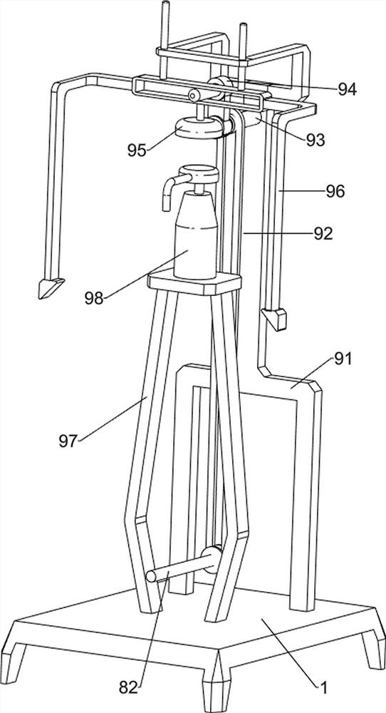
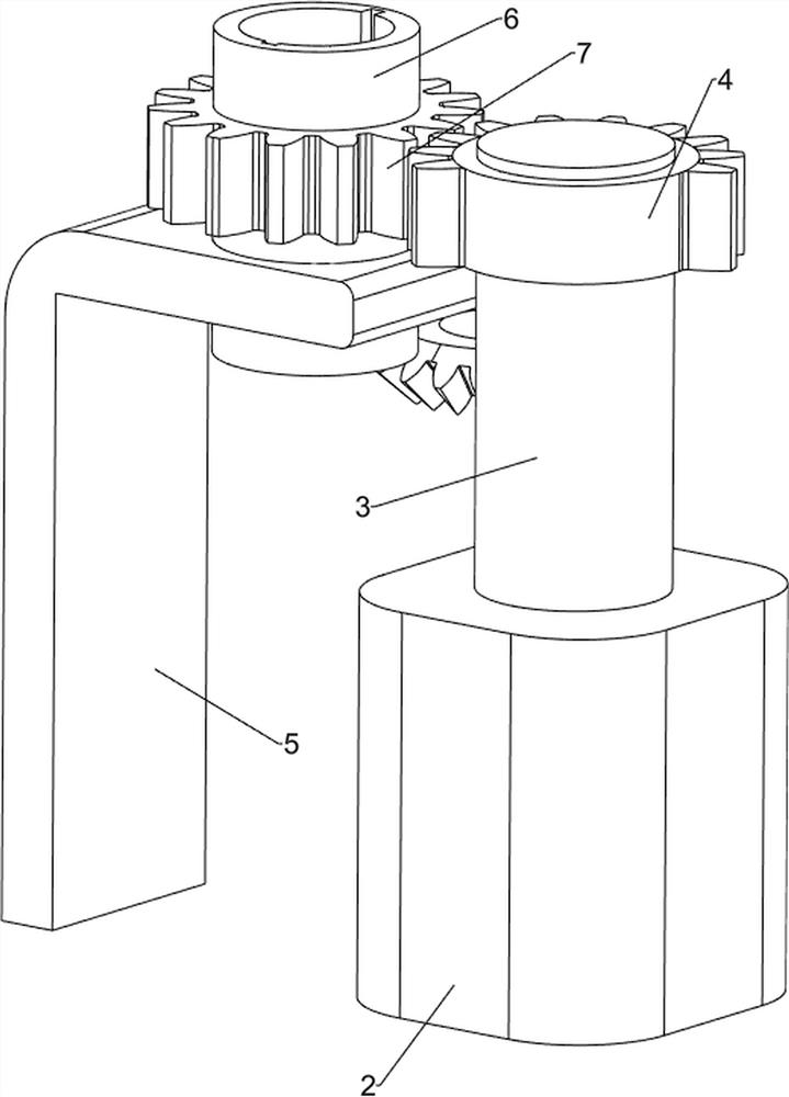
[0056] A test tube sterilization and disinfection device, such as Figure 1-4 As shown, it includes a bottom plate 1, a motor 2, a first rotating shaft 3, a missing gear 4, a first support column 5, a sliding sleeve 6, a first spur gear 7, an oscillation mechanism 8 and a pressing mechanism 9. There is a motor 2, the top of the output shaft of the motor 2 is provided with a first rotating shaft 3, the upper part of the first rotating shaft 3 is provided with a missing gear 4, the left rear side of the top of the bottom plate 1 is provided with a first support column 5, and the upper part of the first support column 5 is connected in a rotational manner There is a sliding sleeve 6, the sliding sleeve 6 is provided with the first straight gear 7, the first straight gear 7 cooperates with the missing gear 4, the base plate 1 is provided with an oscillating mechanism 8, the 8 components of the oscillating mechanism are connected with the sliding sleeve 6, the base plate 1 and the ...

Embodiment 2

[0061] On the basis of Example 1, such as Figure 5-7 As shown, a heating mechanism 10 is also included. The heating mechanism 10 includes a fourth support column 101, a second wedge block 102, a spring 103 and a heating plate 104. The left side of the top of the bottom plate 1 is symmetrically provided with the fourth support column 101. The tops of the four support columns 101 are all slidably connected with a second wedge block 102 , five springs 103 are arranged inside the second wedge block 102 , and a heating plate 104 is arranged between the springs 103 on the same side.

[0062] People put the test tube on the top block 88, start the heating plate 104, and when the first wedge-shaped block 96 moves down to contact with the second wedge-shaped block 102, it drives the second wedge-shaped block 102 to move inwardly, and then drives the heating plate 104 to move toward the inside. The inside moves, and when the heating plate 104 moves to contact with the test tube, the se...


PUM


Abstract

The invention relates to a disinfection device, in particular to a test tube sterilization and disinfection device. The technical problem of the invention is to provide the test tube sterilization and disinfection device capable of improving the washing efficiency. The test tube sterilization and disinfection device comprises a bottom plate and a motor, and the motor being arranged on one side of the bottom plate; a first rotating shaft, arranged on an output shaft of the motor; a missing gear, the first rotating shaft being provided with the missing gear; a first supporting column, arranged on one side of the bottom plate; a sliding sleeve, the first supporting column being rotationally connected with the sliding sleeve; a first straight gear, the sliding sleeve being provided with the first straight gear, and the first straight gear being matched with the missing gear; and a vibration mechanism, arranged on the bottom plate, and the vibration mechanism part being connected with the sliding sleeve. By arranging the clamping mechanism and the limiting mechanism, people do not need to manually fix the test tube, and when the test tube moves up and down, the test tube can be prevented from swinging left and right.

Description

technical field [0001] The invention relates to a disinfection device, in particular to a test tube sterilization and disinfection device. Background technique [0002] In the daily work of the laboratory department of the hospital, the used test tubes need to be scrubbed and cleaned for later use. The commonly used test tube brushes are usually manually operated, with a relatively simple structure and only have the function of scrubbing. Laborious, the existing electric test tube brush is inconvenient to use, difficult to hold and operate, has a large vibration, and only has the function of rotating scrubbing. It needs to be used with a faucet or a liquid outlet pipe, and does not have the function of automatically adding cleaning solution or disinfectant , Affect the efficiency of test tube scrubbing, be unfavorable for clinical popularization and use, increase work difficulty to laboratory staff. [0003] Therefore, need to develop a kind of test tube sterilization and d...

Claims


Application Information

Patent Timeline
IPC IPC(8): A61L2/18A61L2/04A61L2/26
CPCA61L2/04A61L2/18A61L2/26A61L2202/23
Inventor 范桂花
Owner 范桂花
Why Eureka
Try Eureka