Straw cleaning machine with waterflow stirring, mechanical feeding and positioned cleaning functions

A technology of positioning cleaning and mechanical addition, which is applied in the cleaning field, can solve the problems of large maintenance costs, achieve the effects of reducing maintenance times, preventing left and right swings, and reducing maintenance costs

Inactive Publication Date: 2016-06-29
CHONGQING XIPU AGRI DEV CO LTD
View PDF0 Cites 0 Cited by
  • Summary
  • Abstract
  • Description
  • Claims
  • Application Information

AI Technical Summary

Problems solved by technology

But in the process of application, it is found that the power mechanism is often maintained, which brings a lot of maintenance costs. After analysis, it is mainly because the cleaning tank has a certain swing when it moves up and down.

Method used


Image

  • Straw cleaning machine with waterflow stirring, mechanical feeding and positioned cleaning functions
  • Straw cleaning machine with waterflow stirring, mechanical feeding and positioned cleaning functions

Examples


Embodiment 1

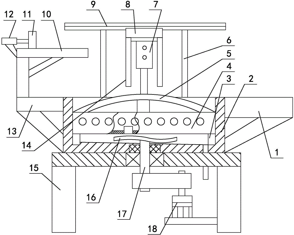
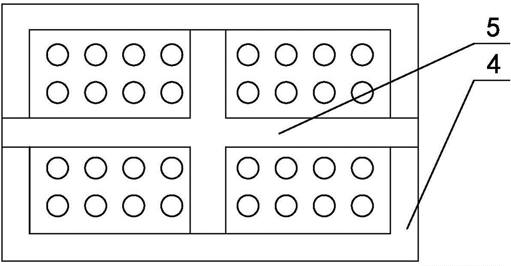
[0023] like figure 1 , figure 2 As shown, the straw cleaning machine with agitating water flow, mechanical feeding and positioning cleaning includes a cleaning tank 2, and a cleaning tank 4 for placing straws that moves up and down in the cleaning tank 2 is provided. The bottom and side walls of the cleaning tank 4 are Leakage holes are all provided, and the inner wall of the cleaning tank 2 at the bottom of the cleaning tank 4 is fixed with a stopper 3 for preventing the bottom of the cleaning tank 4 from contacting the bottom of the cleaning tank 2, and a bracket 6 is installed on the top of the cleaning tank 2. A slide rail 9 is arranged horizontally, and a slide block 8 that slides left and right is installed on the slide rail 9. A power mechanism 7 for cleaning the tank 4 to move up and down is installed at the bottom of the slide block 8. The material table 1 and the slide rail 9 extend to the upper part of the unloading table 1, and a loading table 11 for convenient l...

Embodiment 2

[0027] A change is made on the basis of Embodiment 1, the power mechanism 7 is a cylinder, the cylinder body of the cylinder is installed on the bracket 6, and the piston rod of the cylinder is connected with the handle 5; the inclination angle of the inclined surface is changed to 20 degrees. Others are the same as embodiment one.

Embodiment 3

[0029] Changes are made on the basis of Embodiment 1. The power mechanism 7 includes a screw and a nut that cooperate with each other. The lower end of the screw is vertically fixed on the handle 5, and the upper end passes through the bracket 6 independently. The nut is arranged above the bracket 6. The gear set is connected with the power transmission of the motor; the inclination angle of the inclined surface becomes 16 degrees. Others are the same as embodiment one.


PUM

PropertyMeasurementUnit
Slopeaaaaaaaaaa

Abstract

The invention relates to a straw cleaning machine with waterflow stirring, mechanical feeding and positioned cleaning functions and belongs to the technical field of cleaning. The straw cleaning machine comprises a cleaning water tank. A cleaning tank which is capable of moving up and down and is used for containing straw is arranged in the cleaning water tank. Check blocks are fixed to the inner side wall of the portion, below the cleaning tank, of the cleaning water tank. A support is installed at the top of the cleaning water tank. A sliding rail is transversely arranged on the support. A sliding block capable of sliding leftwards and rightwards is installed on the sliding rail. A power mechanism used for driving the cleaning tank to move up and down is installed at the bottom of the sliding block. A charging table capable of facilitating charging is arranged on the left side wall of the cleaning water tank. A charging plate is installed on the charging table, and a pushing plate is arranged on the charging plate. A stirring blade is installed in the space between the cleaning tank and the cleaning water tank. At least one vertically-arranged guide rod is arranged on the sliding block. By the adoption of the straw cleaning machine, the cleaning tank is effectively prevented from swinging leftwards and rightwards when moving up and down, the number of maintenance times is decreased, and the maintenance cost is reduced.

Description

technical field [0001] The invention relates to a straw cleaning machine with stirring water flow, mechanical feeding and positioning cleaning, belonging to the technical field of cleaning. Background technique [0002] With the continuous advancement of technology, people are using more and more straw for ingredients when producing pig feed, cattle feed, horse feed and sheep feed. The cost is relatively low, and it does not affect the animal's food intake. There is also the effect of promoting digestion. However, when producing straw feed, the straw needs to be cleaned at first, and the existing method is to use manual cleaning, which is labor-intensive and time-consuming, and manual management is also relatively complicated. [0003] In the last month, the inventor designed a whole set of devices to solve the above problems. When cleaning the straw, it reduces the number of cleaning staff, saves costs, and has high cleaning efficiency. Compared with manual management, its...

Claims


Application Information

Patent Timeline
IPC IPC(8): B08B3/10B08B13/00
Inventor 钟万祥
Owner CHONGQING XIPU AGRI DEV CO LTD
Why Eureka
Try Eureka