Switch device and transmission structure thereof

A technology of transmission structure and switchgear, which is applied in the direction of electric switch, contact drive mechanism, high voltage/high current switch, etc. It can solve the large sliding friction force of the limit plate and the pin shaft, and the high power requirement for the opening and closing of the operating mechanism , Low reliability of switchgear and other problems, to achieve the effect of reducing sliding friction, improving service life and reducing wear

Active Publication Date: 2019-04-19
XUJI GRP +3
View PDF6 Cites 0 Cited by
  • Summary
  • Abstract
  • Description
  • Claims
  • Application Information

AI Technical Summary

Problems solved by technology

[0004] The purpose of the present invention is to provide a transmission structure to solve the problem of large sliding friction between the limit plate and the pin shaft in the existing transmission structure; the purpose of the present invention is also to provide a switch device to solve The switchgear in the prior art has relatively high requirements for the opening and closing power of the operating mechanism and the reliability of the switchgear is relatively low

Method used


Image

  • Switch device and transmission structure thereof
  • Switch device and transmission structure thereof
  • Switch device and transmission structure thereof

Examples


Embodiment Construction

[0030] Embodiments of the present invention will be further described below in conjunction with the accompanying drawings.

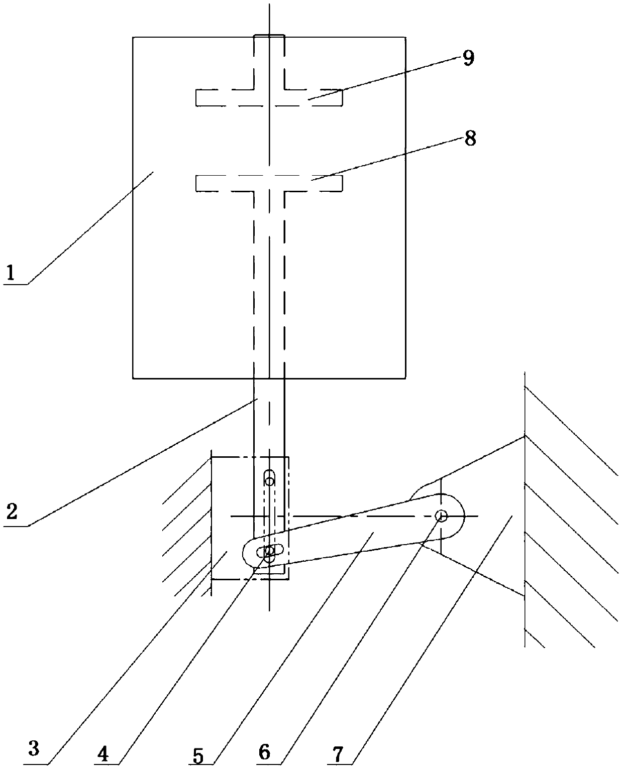
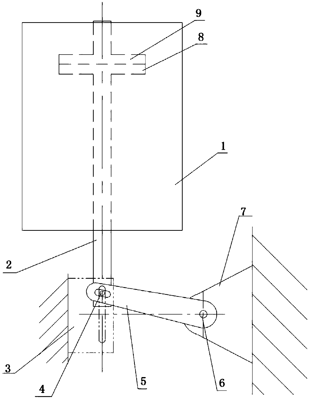
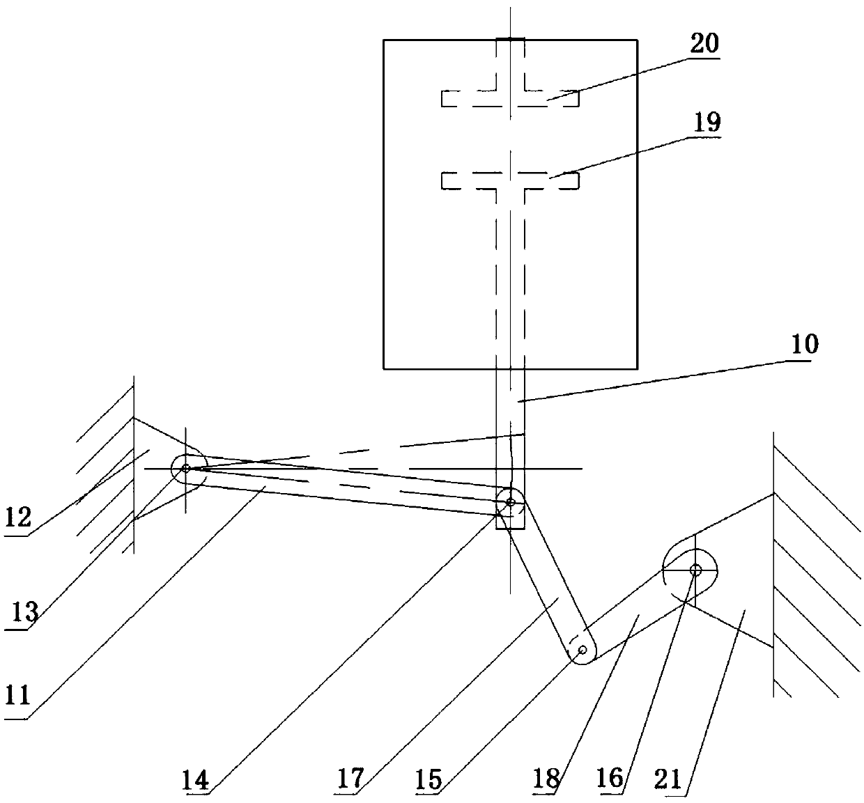
[0031] Specific embodiments of the switching device provided by the present invention, such as image 3 and Figure 4 As shown, the switchgear includes an arc extinguishing chamber, an operating mechanism, and a transmission structure arranged between the arc extinguishing chamber and the operating mechanism. The moving contact 19 and the static contact 20 are arranged in the arc extinguishing chamber. The head 19 is connected to drive the driving rod 10 that the movable contact 19 contacts or separates from the static contact 20. The lower end of the driving rod 10 is provided with a second pin shaft 14, and the driving rod 10 is hinged for driving through the second pin shaft 14 at the same time. The limit rod 11 for the limit of the rod 10 and the power input rod for driving the driving rod 10 to move, the other end of the limit rod 11 is hinged on t...


PUM


Abstract

The invention relates to a switch device and a transmission structure thereof. The switch device comprises an arc extinguishing chamber, an operating mechanism and a transmission structure disposed between the arc extinguishing chamber and the operating mechanism, the arc extinguishing chamber is internally provided with a moving contact, the transmission structure comprises a drive rod having oneend passing through the arc extinguishing chamber to connect with the moving contact to drive closing and opening of the moving contact, the drive rod is hinged with a spacing rod and a power input port configured to drive motion of the drive rod through the same hinge structure, the power input rod has a rotation power input end being in transmission connection with the operating mechanism, theother one end of the spacing rod is hinged on the fixed pedestal, and the drive rod achieves the direct moving output itself by employing at least one set of the three sets between the spacing rod andthe fixed pedestal, between the drive rod and the arc extinguishing chamber and between the drive rod and the spacing rod; and the transmission mechanism is a transmission mechanism in the switch device. The above technical solution solves the problem that the reliability of the switch device is relatively low and the power required for the opening and closing of the operating mechanism is high in the prior art.

Description

technical field [0001] The invention relates to the technical field of medium-voltage switchgear, in particular to a switchgear and its transmission structure. Background technique [0002] The vacuum switch structure used in the technical field of medium-voltage switchgear generally consists of a moving contact and a static contact, and the opening and closing of the switch is realized by driving the moving contact to move by the operating mechanism. The moving track of the moving contact of the vacuum switch is a straight line and short stroke, while most of the operating mechanisms used to drive the moving contact in the technical field of medium voltage switchgear are spring operating mechanisms, and their power output track is rotary. The mechanism is prone to the following failures: the operating mechanism refuses to open, refuses to close, has no response, the opening and closing distance is not in place, and the operation fails. Therefore, there is a need for a swit...

Claims


Application Information

Patent Timeline
Patent Type & Authority Applications(China)
IPC IPC(8): H01H33/666H01H33/42H01H3/46
CPCH01H3/46H01H33/42H01H33/666H01H2003/466
Inventor 郑晓果赵洪柏吴小钊白维正喻会永王其中曹善军李跃
Owner XUJI GRP
Why Eureka
Try Eureka