Multifunctional anti-floating device for overwater cast-in-place pile reinforcement cage

A reinforcement cage and multi-functional technology, applied in protection devices, sheet pile walls, buildings, etc., can solve problems such as easy deviation of reinforcement cages during lowering, difficulty in installing reinforcement cages in sections, and affecting the quality of cast-in-situ piles, etc., to achieve high practicality value, guarantee installation accuracy and installation quality, and reduce the difficulty of assembly

Active Publication Date: 2021-08-10
CHINA CONSTR EIGHTH ENG DIV
View PDF6 Cites 0 Cited by
  • Summary
  • Abstract
  • Description
  • Claims
  • Application Information

AI Technical Summary

Problems solved by technology

[0003] The purpose of the present invention is to provide a multi-functional anti-floating device for cast-in-situ pile reinforcement cages on water, so as to solve the problems of easy offset during lowering of reinforcement cages, difficulty in segmental installation and easy floating of reinforcement cages that affect the quality of cast-in-situ piles proposed in the background technology And other issues

Method used


Image

  • Multifunctional anti-floating device for overwater cast-in-place pile reinforcement cage
  • Multifunctional anti-floating device for overwater cast-in-place pile reinforcement cage
  • Multifunctional anti-floating device for overwater cast-in-place pile reinforcement cage

Examples


Embodiment Construction

[0022] The following will clearly and completely describe the technical solutions in the embodiments of the present invention with reference to the accompanying drawings in the embodiments of the present invention. Obviously, the described embodiments are only some, not all, embodiments of the present invention. Based on the technical solutions in the present invention, all other embodiments obtained by persons of ordinary skill in the art without making creative efforts belong to the protection scope of the present invention.

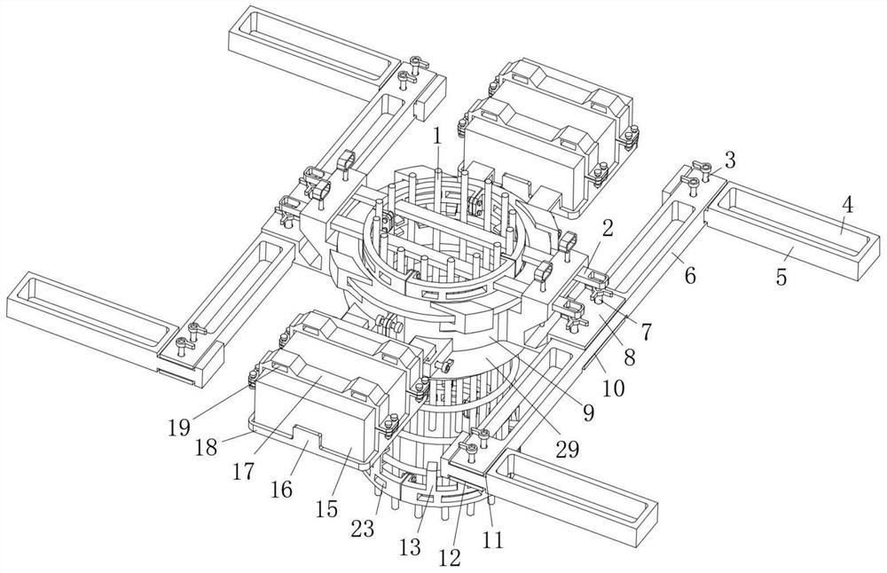
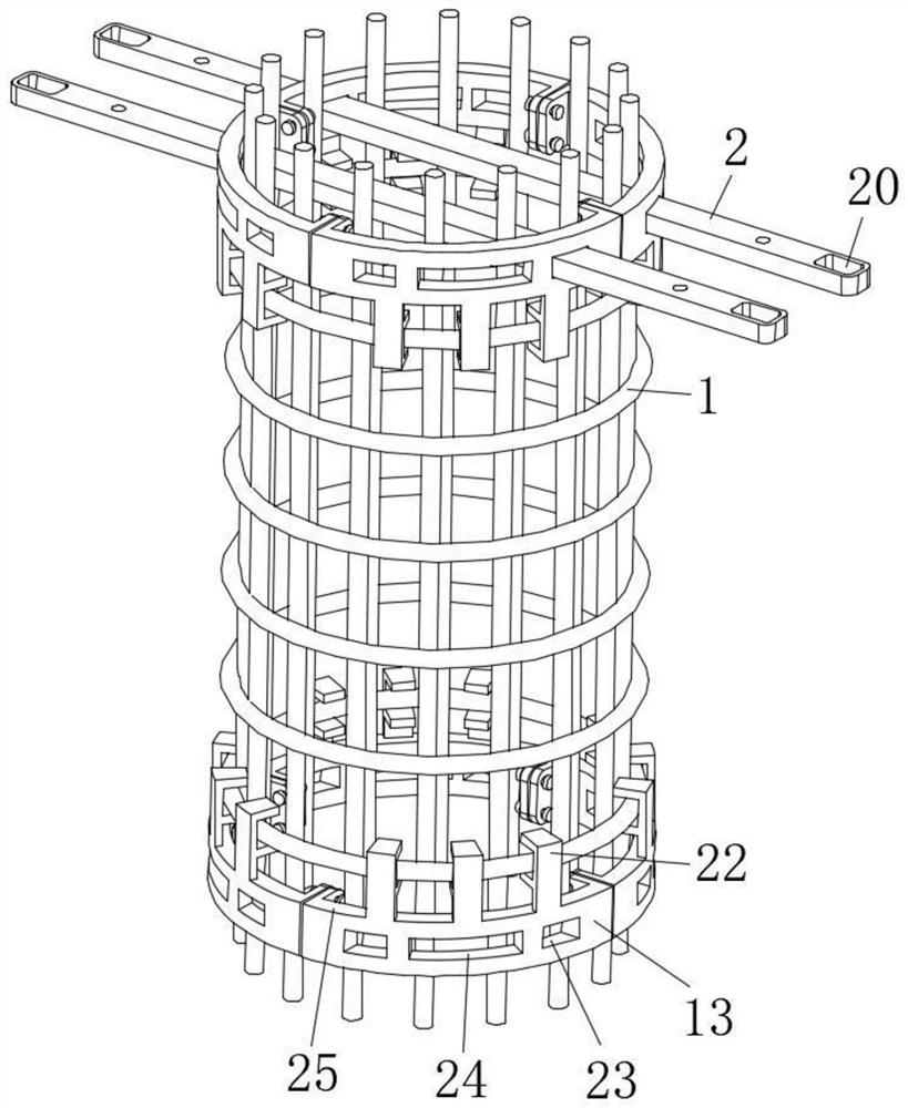
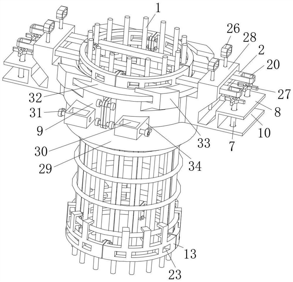
[0023] see Figure 1 to Figure 4 , the present invention provides a technical solution: a multi-functional anti-floating device for a reinforced cage of cast-in-situ piles on water, including a limit clamp 13 fixedly installed at the end of the steel cage 1, and a limit hole is opened on the limit clamp 13 23. The limit clamp 13 is composed of four fan-shaped snap rings 25 connected in series by bolts, and each fan-shaped snap ring 25 is provided with ...


PUM


Abstract

The invention relates to the technical field of cast-in-place piles, in particular to a multifunctional anti-floating device for an overwater cast-in-place pile reinforcement cage. The multifunctional anti-floating device comprises a limiting hoop fixedly mounted at the end part of the reinforcement cage, wherein a limiting hole is formed in the limiting hoop. The multifunctional anti-floating device has the beneficial effects that the designed anti-floating device for the reinforcement cage can effectively utilize the weight of the device to reduce the upward floating force of the reinforcement cage in the pouring process, and meanwhile, the effect can be guaranteed by additionally adding weight increasing blocks according to needs; according to the device, the reinforcement cage can be effectively prevented from deflecting in the lowering process through accurate sleeving sliding of a steel casing and a limiting hoop, so that the mounting precision and the mounting quality of the reinforcement cage can be effectively guaranteed; and the position of the reinforcement cage can be effectively fixed through limiting beams, the positions of the different sections of reinforcement cages are determined through the attachment of the limiting hoops located on the different sections of reinforcement cages, therefore, the safety during the assembly of the reinforcement cages is improved, and the assembly difficulty is reduced.

Description

technical field [0001] The invention relates to the technical field of cast-in-situ piles, in particular to a multi-functional anti-floating device for a reinforced cage of cast-in-place piles on water. Background technique [0002] During the water construction of cast-in-place piles, the required reinforcement cages are produced in sections, and then assembled on site and lowered to the corresponding pile positions, and then concrete is poured into the reinforcement cages to support the cast-in-place piles. However, when the existing segmented steel cage is installed, on the one hand, because the steel cage at the lower end does not have a good limit, it is easy to shift during the lowering process, which affects the quality of perfusion. On the other hand, it is different in the prior art. It is difficult to make a good positioning between the steel cages of the segments and the assembly operation is complicated. At the same time, the reinforcement cage is also prone to ...

Claims


Application Information

Patent Timeline
Patent Type & Authority Applications(China)
IPC IPC(8): E02D5/34E02D13/00E02D31/12
CPCE02D5/34E02D13/00E02D31/12
Inventor 张其兵高贯伟张仲林李贵康刘巨明
Owner CHINA CONSTR EIGHTH ENG DIV
Why Eureka
Try Eureka