Method for replacing 10kV interconnection switch and section switch on load

A technology of tie switch and section switch, which is applied in the direction of overhead lines/cable equipment, etc., can solve the problems of loss, power outage economy, etc., and achieve the effect of reducing the scope of power outages

Pending Publication Date: 2021-08-10
STATE GRID HEILONGJIANG ELECTRIC POWER CO LTD HARBIN POWER SUPPLY CO +1
View PDF0 Cites 0 Cited by
  • Summary
  • Abstract
  • Description
  • Claims
  • Application Information

AI Technical Summary

Problems solved by technology

[0004] The purpose of the present invention is to solve the problem of severe economic loss caused by power failure when the existing tie switch and section switch are replaced, and provides a method for replacing a 10kV tie switch and section switch with load

Method used


Image

  • Method for replacing 10kV interconnection switch and section switch on load

Examples


specific Embodiment approach 1

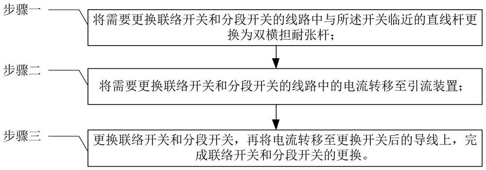
[0014] Specific implementation mode one: the following combination figure 1 Describe this embodiment, the method for replacing a 10kV tie switch and section switch with load described in this embodiment includes:

[0015] Step 1. Replace the linear rod adjacent to the switch in the line that needs to replace the tie switch and the section switch with a tension rod;

[0016] Step 2, transfer the current in the circuit that needs to replace the tie switch and section switch to the diversion device;

[0017] Step 3: Replace the tie switch and the section switch, and then transfer the current to the wire after the switch is replaced, and complete the replacement of the tie switch and the section switch.

[0018] Further, in this embodiment, the tension bar described in Step 1 is a double cross-arm tension bar.

[0019] When a power supply fails during dual power supply, the load of the faulty power supply is transferred to another power supply through the contact switch, thereby...


PUM


Abstract

The invention discloses a method for replacing a 10kV interconnection switch and a section switch on load, belongs to the technical field of power grid hot-line work, and aims to solve the problem of serious economic loss caused by power failure when an existing interconnection switch and an existing section switch are replaced. According to the invention, a linear rod, close to a switch, in a circuit in which an interconnection switch and a section switch need to be replaced is replaced by a double-cross-arm tension-resistant rod, the current in the circuit in which the interconnection switch and the section switch need to be replaced is transferred to a current guide device, and after the interconnection switch and the section switch are replaced, the current is transferred to a lead after the switch is replaced, so that the replacement of the interconnection switch and the section switch is completed; and the method is suitable for replacing the 10 kV interconnection switch and the section switch on load.

Description

technical field [0001] The invention belongs to the technical field of electric power grid live work. Background technique [0002] Whether the structure of the 10kV power distribution system is reasonable and whether the wiring method is flexible and reliable will directly affect the image and economic benefits of the power supply enterprise. Therefore, a large number of tie switches and section switches need to be installed on the 10kV distribution line to realize the "hand in hand" power supply mode. Due to the limitation of power outage conditions, its promotion work has also been greatly constrained. [0003] In addition, after the switch is put into operation, once a fault occurs, it will inevitably result in a power outage of the entire line, which will not only seriously affect the reliability of power supply, but also cause serious economic losses. Contents of the invention [0004] The purpose of the present invention is to solve the problem of serious economic...

Claims


Application Information

Patent Timeline
Patent Type & Authority Applications(China)
IPC IPC(8): H02G1/02
CPCH02G1/02
Inventor 王馨悦罗一诚高博黄敬寒白春龙刘洋董化新张海容
Owner STATE GRID HEILONGJIANG ELECTRIC POWER CO LTD HARBIN POWER SUPPLY CO
Why Eureka
Try Eureka